Service And Parts Q-tabletop
This document was uploaded by user and they confirmed that they have the permission to share it. If you are author or own the copyright of this book, please report to us by using this DMCA report form. Report DMCA
Overview
Download & View Service And Parts Q-tabletop as PDF for free.
More details
- Words: 2,731
- Pages: 18
Model “Q” Music Center Version 2.4 ~ Service & Parts Manual
1
Copyright © 2008 All Rights Reserved Rock-Ola Manufacturing Corporation 2335 208th Street, Torrance, CA 90501
This document contains information proprietary to Rock-Ola Manufacturing Corporation and may not be reproduced, published or distributed in any form or disclosed in whole or in part without written authorization.
2
SAFETY INSTRUCTIONS
IMPORTANT! a.
Read these instructions.
b.
Keep these instructions.
c.
Follow all instructions.
d.
Do not use this apparatus near water.
e.
Clean only with dry cloth.
f.
Do not block any ventilation openings. Install in accordance with the manufacturer’s instructions.
g.
Do not install near any heat sources such as radiators, heat registers, stoves, or other apparatus (including amplifiers) that produce heat.
h.
Do not defeat the safety purpose of the polarized or grounding-type plug. A polarized plug has two blades with one wider than the other. A grounding-type plug has two blades and a third grounding prong. The wide blade or the third prong are provided for your safety. If the provided plug does not fit into your outlet, consult an electrician for replacement of the obsolete outlet.
i.
Protect the power cord from being walked on or pinched particularly at plugs, convenience receptacles, and the point where they exit from the appliance.
j.
Only use attachments/accessories specified by the manufacturer.
k.
Unplug this apparatus during lightning storms or when unused for long periods of time.
l.
Refer all servicing to qualified service personnel. Servicing is required when the apparatus has been damaged in any way, such as power-supply cord or plug is damaged, liquid has been spilled or objects have fallen into the apparatus, the apparatus has been exposed to rain or moisture, does not operate normally, or has been dropped.
WARNING: Terminals marked with the lightning flash per are hazardous live and the external wiring connected to these terminals requires installation by an instructed person or the use of ready-made leads or cords.
3
TABLE OF CONTENTS
SAFETY INSTRUCTIONS......................................................................................................................................................... 3 IMPORTANT! ............................................................................................................................................................................... 4 SAVE THE PACKING MATERIAL AND CARTON!............................................................................................................................. 4 THE MATERIAL USED TO PACK YOUR JUKEBOX HAS BEEN SPECIFICALLY DESIGNED FOR THIS MODEL. SHOULD YOU HAVE NEED TO RETURN THE UNIT FOR SERVICE OR WARRANTY, PLEASE FOLLOW THE ................................................................................... 4 REPACKING INSTRUCTIONS ON PAGE 13...................................................................................................................................... 4 “Q” MUSIC CENTER - SPECIFICATIONS............................................................................................................................ 5 ZONE CONNECTIONS WITH EXTERNAL SPEAKERS..................................................................................................... 6 Single Zone Stereo.................................................................................................................................................................. 7 Dual Zone Mono .................................................................................................................................................................... 8 BLOCK DIAGRAM ................................................................................................................................................................... 8 BLOCK DIAGRAM .................................................................................................................................................................... 9 CLEANING THE TOUCH SCREEN ........................................................................................................................................ 9 TROUBLESHOOTING CHARTS ........................................................................................................................................... 10 Power Problems ................................................................................................................................................................... 10 Amplifier Problems .............................................................................................................................................................. 10 SERVICE & MAINTENANCE ................................................................................................................................................ 10 REPACKING INSTRUCTIONS .............................................................................................................................................. 11 PARTS CATALOG ................................................................................................................................................................... 13 OUTER CABINET ....................................................................................................................................................................... 13 .................................................................................................................................................................................................. 13 INSIDE CABINET..................................................................................................................................................................... 14 ACCESSORIES.......................................................................................................................................................................... 16 WIRELESS BRIDGE KIT, #02467................................................................................................................................................ 16 USING A WI-FI BRIDGE ............................................................................................................................................................. 16 DIAL-UP MODEM KIT, #02466 .................................................................................................................................................. 16 USING A DIAL-UP ADAPTER ...................................................................................................................................................... 16
Important! Save the packing material and carton! The material used to pack your jukebox has been specifically designed for this model. Should you have need to return the unit for service or warranty, please follow the Repacking Instructions on page 13. 4
“Q” Music Center - Specifications Dimensions: Uncrated: Height Width Depth Crated: Height Width Depth
Weight: Uncrated Crated
26” 22” 11”
66 cm 55.88 cm 28 cm
32” 27” 17”
81.28 cm 68.58 cm 43.18 cm
62 lbs 69 lbs
28.12 kg 31.3 kg
Amplifier: Output Power:
90 wRMS /ch @ 4 ohms
Protection:
Speaker overload Over voltage Under voltage
Frequency:
30 - 20,000 Hz North America
Export
115VAC
230VAC
50/60 Hz
50/60 Hz
260 watts max./145 standby wattage 2.25 amps max / 1.25 standby amps
260 watts max./145 standby wattage 1.12 amps max / 0.63 standby amps
Voltage: Frequency: Power Consumption:
Core: Processor RAM Software
Pentium 4 512 MB QSonix V2.1
Speakers:
(2) 3-1/2” full range
Monitor:
15” SAW Touch-Monitor
5
Zone Connections with External Speakers The Rock-Ola Music Centers offer several methods of connecting to external speakers or music systems. Take note of the following when planning your Music Center speaker connections.
There are two modes of operation for the speaker system. These are Single Zone Stereo and Two Zone Mono.
In the Single Zone Stereo mode, the jukebox speakers as well as any external speakers connected to the speaker terminals will play in stereo. The on-screen zone 1 volume slider will control all of the speakers. If another zone such as speakers on a patio or in another room is desired, an additional amplifier will need to be connected to the zone 2 RCA jacks. That zone will then have the volume controlled by the on-screen zone 2 volume slider. If a powered sub-woofer is to be used, it is connected to the zone 1 RCA jacks as shown in the Single Zone Stereo diagram on the next page.
A set of “fixed” output RCA jacks, labeled FIXED OUT on the connection panel, provide a high level, unbalanced signal to connect to a receiver or integrated amplifier. The output is roughly the same as the output of a CD player or tuner. All control of volume is done at the receiver. In this case, the volume sliders on the screen have no effect on this output. There are also two sets of RCA jacks that can be used to drive external power amplifiers, powered sub-woofers, or a stereo receiver. The volume of these outputs is controlled by the on-screen volume sliders. The number button to the left of the volume slider denotes which zone is being adjusted.
If two zones of speakers are desired without the use of an additional amplifier, the Two Zone Mono mode allows the splitting of the channels into the two zones. Connect any external speakers in the same room as the jukebox to the “Zone 1” speaker terminals. Connect the external speakers for the second zone to the “Zone 2” speaker terminals. Set the mode switch to the “2 Zone Mono” mode. The onscreen zone 1 volume slider will control the jukebox and the external speakers in the same room. The on-screen zone 2 volume slider will control the second set of speakers. The right and left channels will be combined into a mono signal so no loss of program material will occur. If a powered sub-woofer is to be used, it is connected to the zone 1 RCA jacks as shown in the Dual Zone Mono diagram.
When connecting to external amplifiers or receivers located a long distance away, a hum may be noticed. The use of an isolation device in the audio line may be necessary to correct a “ground loop”. When connecting external speakers be sure the load impedance is 4 to 8 ohms. Do not connect more than 2 speakers to a channel.
GOOD TO KNOW: Power is limited to the jukebox speakers. Full power is available to the external speakers and therefore high-efficiency speakers will play much louder than the internal speakers. This is normal.
NOTE: In the event of a speaker output overload, the power amplifier will automatically shut down. To reset the amplifier, shut down the jukebox by pressing the blue power button. When the system has shut down, turn the main power switch/circuit breaker off for 30 seconds. Turn the main switch back on and press the blue button to restart the system. The amplifier will resume operation. Turn down the volume or reduce the equalizer settings to avoid this in the future.
WARNING:
Do NOT unplug or connect RCA plugs with the power amplifier(s) on. The resulting hum or noise may damage the speakers.
6
Single Zone Stereo The Zone 1 slider on the touchscreen controls the volume of the jukebox and the external speakers together.
7
Dual Zone Mono The onscreen Zone 1 slider will control the volume of the jukebox and the external speakers connected to the Zone 1 terminals. The onscreen Zone 2 slider will control the volume of the speakers connected to the Zone 2 speaker terminals.
NOTE: Power is limited to the jukebox speakers to prevent unwanted vibration of the drives and protect the cabinet. Full power is available to the external speakers therefore high efficiency speakers will be much louder than the jukebox. This is normal.
8
Block Diagram SPEAKER TERMINAL BLOCK 100uF NP
4 3 2 1
XFRMR, AMP
IEC INLET/FILTER
1 ZONE STEREO POWER AMPLIFIER
CIRCUIT BREAKER
115V
1 2 3
MODE SW
SW SPDT LEFT SPEAKER
2 ZONE MONO
1 2 3 4
100uF NP
CON4
RIGHT SPEAKER
CON3 SW SPDT 230V
7 6 5 4 3 2 1
CABLE TO ATX PS
CON7
59149-A-LF
1 RING TERM. MINIFIT, 8PL 3.5MM STEREO
ATX SUPPLY
2 4 6 8
1 3 5 7 JST X 2
INT AMP OUT
CONTROL IO
RCA JACK
2 1
MODE SW
AUX IN
AUX IN
3.5MM STEREO
1 2 3 4
1 2 3 4
1 2 3 4
1 2 3 4
3.5MM STEREO
AUDIO CONTROL
TO DVD DRIVE
1 2 3 4
1 2 3 4
TO HDD
MAIN IN
1 2 3 4
CON4
CON4
JST x 3 1 2 3
CCFL TUBES INVERTER
MOTHERBOARD LED CLUSTER
LED CLUSTER LED CLUSTER
LED CLUSTER
LED CLUSTER LED CLUSTER
LED CONTROLLER
MONITOR
VGA
SERIAL
3.5MM STEREO LINE OUT USB 1
4 3 2 1
IR Recvr.
EXTERNAL USB
USB 2
1 2 3 4
LAN
1 3 5 7 9
2 4 6 8 10
5x2 POWER BUTTON
LAN
Cleaning the Touch Screen Any standard glass cleaner can be used to clean the touchscreen. Always spray the glass cleaner on the cloth or towel and clean the touchscreen. Glass cleaner sprayed directly on the monitor could possibly leak inside and cause damage. 9
Troubleshooting Charts Power Problems Fault
Symptom
Possible Cause • •
Power Switch Dark Jukebox fails to operate at all when it is plugged in and the blue power button has been pressed
• •
• Power Switch Lit
•
Main Power switch not on Plug not seated in wall outlet or jukebox Outlet "Dead" "Tripped" Circuit Breaker on Power Switch Overload. Turn off for 10 minutes and retry Defective ATX power supply – Refer to qualified technician.
Amplifier Problems Fault Amplifier "Dead" NOTE: Be Sure a selection is playing. Screen should say, “Now Playing”
Symptom
Possible Cause
Connect headphones or sound speakers Amplifier protection activated to fixed output Sound Disconnected speakers
No sound
Refer to Qualified Technician
Service & Maintenance Important: There are no user-serviceable components inside the cabinet. Refer all service to a Qualified Technician.
10
Repacking Instructions If you need to send the jukebox out for service, you will need to repack it in its original material. You should have saved the following: Rock-Ola packing crate – bears the model and serial numbers of the unit Pair of foam blocks custom-fitted to the unit Large, heavy, protective plastic bag Steps to re-packing the Mystic jukebox:
Resassemble the crate if necessary. Secure the bottom with packing tape. Make sure that the “THIS SIDE UP” arrows are pointing toward the open end of the box.
On a protected surface, cover the jukebox with the protective bag from the top down. With the bag on, reposition the jukebox carefully on it’s back. Enclose the jukebox completely in the bag. Seal with some tape.
11
The foam packing blocks are not the same, each fits specifically the right and left sides of the jukebox. Figure out which of the blocks fit the right and left sides of the jukebox.
Fit the first block to the corresponding side of the jukebox. You may want another pair of hands to lift the machine while you fit the foam on the cabinet side.
Place the remaining block over the other end of the jukebox, as previous. Carefully slide the wrapped and blocked jukebox into the crate from the top, base first. The jukebox and protected packing material should now fit snugly in the crate. Seal the crate – it’s ready for shipping.
12
Parts Catalog Outer Cabinet
Item No. 1 2 3 4 5 6 7 8
Part No. 57774 59993 57710 61914-LF 61946-LF 60224 61945-A-LF 57577
Description Metal, Top Trim, Claw (3) Red Plastic Cap Monitor, 15” Mungtube Plastic Pilaster (2) Logo, Front Door Trim, “V” side-machined (4) Brass Name Plate/AACO Wings
Item No. 9 10 11 12 13 14 15
13
Part No. 57719 REF 57787 57660 61918-LF 61500-A-LF 61501-LF
Description Grille, Red Plastic (2) Base Grille Casting, Chrome plate Grille cloth Power Button Harness assy USB Connector harness assy CD-RW Drive
Inside Cabinet
Item No. 1 2 3 4 5 6 7
Part No.
Description
61920-LF 61486-LF 60861-1A-LF 61527-A-LF SV-61892-A 59927-A-LF 61903-LF SV-651916-A
Motherboard enclosure Motherboard Assy Power Supply Assy., ATX HDD, 160 GB, Programmed QB8 Remote Audio Interface CCFL Lamp Transformer Assy – new pix Power Amp PC Board
Item No. 8 9 10 11 12
14
Part No.
Description
61896-LF 61901-LF 59946 57389-LF SV-60936-A-LF 61005-A
Power Switch/Circuit Breaker, 115V Power Switch/Circuit Breaker, 230V Speaker 3”, R91 (2 pl) Universal bracket LED Controller Inverter PC Board
Harnesses Part No.
Description
60833-A 60834-A 61942-A-LF 61939-A-LF 61915-A-LF 61535-A-LF 61938-A-LF 61769-A-LF 61950-A-LF 61500-A-LF 61918-A-LF 61919-A-LF 61941-A-LF 61940-A-LF 61944-A-LF 61938-A-LF 59927-A-LF 61943-A-LF
VGA Harness (comes with monitor) Serial Harness ( comes with monitor) Main Power Harness Harness, Power Amp Input Transformer harness Cable, IDE, 24” round (2) Harness, Speaker “Q” Shielded Audio Cable, 3.5mm – 3.5 mm Harness, Aux Audio Input Harness, USB Extension Harness Assy, Power Button Harness, cat 5, 12” LED Power Harness Harness, Monitor power, Mungsube Harness Assy, Gound jumper “Q” Harness, LED jumper 6” CCFL Light Tube Harness Ground Harness, 3 Lug
59149-A-LF
(230 V CE unit only) Harness Assy Jumper 2” Blue
15
Accessories Wireless Bridge Kit, #02467
Dial-up Modem Kit, #02466
The Wireless Bridge Kit allows the Q to communicate over a wireless (WIFI) network. In addition to the kit you will need
The Dial-Up Modem Kit allows the QB8 to obtain album cover art and data using a conventional telephone line. In addition to the kit you will need
A WIFI available at the point where the jukebox is located.
A dial-up account with an Internet Service Provider such as MSN, AOL, EarthLink, etc.
A personal computer. You will need to program the bridge with the identity of the WIFI access point and security passwords (if used) using a PC before connecting it to the jukebox.
A personal computer. You will need to program the dialup telephone number, access name and password into the modem using a PC before connecting it to the jukebox.
Using a Wi-Fi Bridge
Using a Dial-up adapter
Follow the instructions that come with the bridge to connect to your Wi-Fi network.
Connect to a PC. If your phone line has a call waiting feature, be sure to disable it before attempting to program using a dial-up adapter
Program the bridge with the WEP password if secure encryption is used.
Follow the instructions with the adapter.
Connect LAN cable to the LAN port on the Music Center Unit. Turn the system on.
To program dial-up access numbers, user name, and password.
Touch the Toolbox icon in the Menu Bar on-screen.
Disconnect the dial-up adapter from the PC.
Touch Network Settings tab.
Install in the jukebox next to the core.
Touch Auto Configure. The system should find the Qsonix home.
Connect the power cable to the power-in transfer box.
Now you are ready to rip your CDs into the system!
Turn the system on.
Connect LAN cable to the core.
Touch the Toolbox icon in the Menu Bar on-screen. Touch Network Settings tab.
The Wireless-G Bridge (Linksys Model No. WET54G) may be purchased from Rock-Ola directly or off the shelf at your local computer store.
Touch Auto Configure. The system should find the Qsonix home. Now you are ready to rip your CDs into the system!
A word about the kits...The jukebox does not need a dedicated connection. Since it only communicates with the internet when CD's are being loaded or updates are being run during the maintenance cycle, a temporary connection can be made when adding music and/or running the maintenance cycle for system updates. However, both the Wireless Bridge and Dial-up Adapter kits require user programming with a PC in order to prepare them for the jukebox.
16
Accessories
Part No.
Description
02467
Wireless Bridge Kit
02466
Dial-Up Modem Kit
17
61743-01 Music Center Version 2.4 ~ Q-Model Service & Parts Manual
18
Related Documents

Service Parts
June 2020 11
Service And Parts Q-tabletop
June 2020 4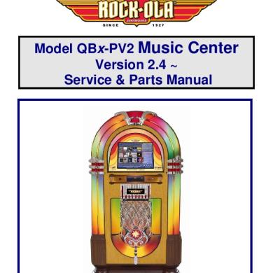
Service And Parts Qbx-pv2
June 2020 1
A22 Service Parts Catalog
December 2019 20
