Caleffi Thermostatic High Flow Mixing Valve With Interchangeable Cartridge For Solar Systems Specifications
This document was uploaded by user and they confirmed that they have the permission to share it. If you are author or own the copyright of this book, please report to us by using this DMCA report form. Report DMCA
Overview
Download & View Caleffi Thermostatic High Flow Mixing Valve With Interchangeable Cartridge For Solar Systems Specifications as PDF for free.
More details
- Words: 1,564
- Pages: 4
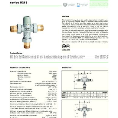
Thermostatic mixing valve with interchangeable cartridge for solar systems
CALEFFI
2523 series
01129/05 GB
Function The thermostatic mixing valve is used in systems for the production of domestic hot water. It is designed to maintain the set temperature of the mixed water supplied to the user when there are variations in the temperature and pressure conditions of the incoming hot and cold water or in the flow rate. This particular series of mixing valves has been designed specifically for systems requiring high flow rates and can function continuously at the high temperatures of the incoming hot water from the solar storage tank.
Product range 2523 series
Thermostatic mixing valve with interchangeable cartridge for solar systems
Technical specifications
Sizes 1/2” - 3/4”
Dimensions
Materials:- body: brass EN 12165 CW617N, chrome-plated - cartridge and shutter: brass EN 12164 CW614N, electroless nickel plated - springs: stainless steel - seal components: EPDM 30-65°C ±2°C
2
MIN
MAX 7
A
110°C
Max inlet temperature:
CALEFFI
Min flow rate to ensure stable temperature:
1/2”: 6,7 l/min 3/4”: 8,4 l/min
E
2:1
Max inlet pressures ratio (H/C or C/H):
Connections:
1
A
14 bar 5 bar 0,2 bar
D
Max working pressure (static): Max working pressure (dynamic): Min working pressure (dynamic):
B
F
Setting range: Accuracy:
C B
1/2” and 3/4” M with union
A
Code 252340 252350
A 1/2” 3/4”
B 85 85
C 170 170
D 169 169
E 95 95
F 74 74
Weight (kg)
1,65 1,68
Solar systems - high temperatures In solar systems with natural circulation in the primary circuit and storage tank with heating jacket, the temperature of the water in the storage tank can vary considerably depending on the degree of solar radiation, and can reach very high temperatures over long periods. In summer, and if there is little water usage, the hot water at the storage tank outlet can actually reach temperatures around 98°C before the pressure and temperature safety valves are actuated. At these temperatures, the hot water cannot be used directly, because of the danger of scalding. Water temperatures over 50°C can cause burns very quickly. For example, at 55°C, partial burn occurs in about 30 seconds, whereas at 60°C partial burn occurs in about 5 seconds. Consequently, the thermostatic mixing valve installed must be able to: • reduce the temperature of the water supplied through the hot water system to a lower value than to the storage tank, i.e. a value usable by the consumer. For reasons of safety, we advise adjusting the temperature of the mixed water supplied to the user to a value not higher than 50°C. • maintain a constant temperature in the mixed water when there are variations in the inlet temperatures and pressures. • maintain function and efficiency over time, without being affected by continuous high temperature of the hot water at the inlet. • ensure that water is stored at high temperature for longer periods, and supplied to the water system at a lower temperature.
Operating principle
High heat resistance The internal flow regulation components are designed to maintain performance of the mixing valve with inlet hot water temperatures up to 110°C, in continuous operation.
HOT
Construction details
COLD
The controlling element of the thermostatic mixing valve is a temperature sensor fully immersed in the mixed water outlet passage which, as it expands or contracts, continuously establishes the correct proportion of hot and cold water entering the valve. The regulation of these flows is by means of a piston sliding in a cylinder between the hot and cold water passages. Even when there are pressure drops due to the drawing off of hot or cold water for other uses, or variations in the incoming temperature, the mixer automatically regulates the water flow to obtain the required temperature.
Interchangeable cartridge The internal cartridge containing all the control components is preassembled in a single body and can easily be inspected for cleaning or replacement if necessary, without any need to take the valve body out of the pipework. Wearproof coating All functional parts, such as the shutter, valve seats and guides, are electroless nickel plated. This wearproof coating minimizes the risk of scale forming and ensures performance is maintained over time. Low-inertia thermostat The most temperature-sensitive element, the “engine” of the thermostatic mixer, has low thermal inertia; in this way it can quickly react to changes in the conditions of inlet pressure and temperature, shortening the valve response time. Temperature setting and locking The control knob permits temperature setting between minimum and maximum in one turn (360°). It also has a tamper-proof system to lock the temperature at the set value.
MIXED
Hydraulic characteristics
Temperature adjustment table
∆p (bar)
1/2”
3/4”
∆p (m w.g.)
1,5
15
1,0
10
Position
Min
1
2
3
4
5
6
7
Max
T (°C)
25
29
33
39
43
48
52
58
65
Reference values: Thot = 68°C; Tcold = 13°C; Hot and cold water inlet pressures = 3 bar
0,5
5
0,3
3
0,2
2
Locking the setting
0,5
50
2 20
1 10
5
0,05
Recommended FLOW RATES to ensure stable operation and an accuracy of ± 2°C
1/2” 3/4”
Kv (m3/h) 4,0 4,5
1/2” 3/4”
Minimum (l/min) 6,7 8,4
2 3
1 MIN
MA
X
7
Flow rate (l/min) (m3/h)
1
0,5
0,1
Turn the knob onto the required number, undo the locking screw, remove the knob and put it back on so that the internal reference couples with the protrusion on the knob carrier ring nut.
Maximum* (l/min) 82,0 92,0
* ∆P = 1,5 bar Use 2523 series thermostatic mixing valves are typically installed at the outlet of hot water storage tanks in solar systems, to ensure constant temperature of the mixed water supplied to the user. 2523 series thermostatic mixing valves, because of their flow characteristics, can be installed in centralised systems with many different user fittings or for controlling groups of fittings, such as shower units, washbasin units, etc. In order to guarantee the delivery of mixed water at the set temperature, the thermostatic mixing valves must have a minimum flow rate of 6,7 l/min (1/2”) and 8,4 l/min (3/4”).
Replacing the cartridge The internal cartridge containing all the control components can be inspected and replaced if necessary, without any need to take the valve body out of the pipework. 1) Close the shut-off valves on the hot and cold inlets. Set the knob to the maximum value. 2) Remove the temperature adjustment knob after unscrewing the lock screw on the top. Remove the plastic knob carrier ring nut. 3) Remove the internal cartridge for inspection or replacement with a new one, using a suitably sized spanner. 4) Fit the knob carrier ring nut back on so that the position indicator is visible. 5) The spare cartridge is supplied preset on the highest value. Then put the control knob back on so that the word MAX align with the position indicator. By turning the knob clockwise it must be possible to make the adjustment from the maximum to the minimum value. Secure the knob with the lock screw. 6) Reopen the shut-off valves and adjust the mixing value onto the required temperature.
Installation Before installing the mixing valve, pipes should be flushed to remove any impurities that could impair performance. We recommend always installing filters of sufficient capacity at the inlet of the water system.
2
3a
3b
4
2523 series thermostatic mixing valves must be installed as shown in the installation diagrams in this leaflet, taking account of the current applicable regulations. 2523 series thermostatic mixing valves can be installed in any position, horizontally or vertically. The following are indicated on the body of the mixing valve: · hot water inlet, indicated with the colour red. · cold water inlet, indicated with the colour blue. Check valves In systems with thermostatic mixing valves, check valves should be installed to prevent undesired back flows. Commissioning In view of the special purpose of the thermostatic mixing valve, it must be commissioned in accordance with current standards by qualified personnel using temperature measuring equipment. Use of a digital thermometer is recommended for measurement of the mixed water temperature. Temperature adjustment The temperature is set at the desired value by means of the knob with the graduated scale, on the top of the valve.
Application diagrams - System with thermal integration Shut-off valve T
Pressure reducing valve Tundish Check valve T/P safety valve T
Temperature gauge 2 1 MIN
CALEFFI CALEFFI
Expansion vessel
M AX 7
Automatic diverting valve T
Thermostat Pump
Normally closed valve
Safety valve
System with thermal integration and recirculation
T
T
2 1 MIN
CALEFFI CALEFFI
MAX 7
Normally closed valve
SPECIFICATION SUMMARIES 2523 Series Adjustable thermostatic mixing valve with interchangeable cartridge for solar systems. 1/2” (1/2” or 3/4”) M connections with union. Brass body. Chrome-plated. Electroless nickel plated brass shutter and cartridge. Stainless steel springs. Seals of EPDM. Maximum inlet temperature 110°C. Adjustment range from 30°C to 65°C. Maximum working pressure (static) 14 bar. Maximum working pressure (dynamic) 5 bar. Accuracy ±2°C. Provided with tamper-proof setting lock.
We reserve the right to change our products and their relevant technical data, contained in this publication, at any time and without prior notice.
CALEFFI CALEFFI S.P.A. · I · 28010 FONTANETO D’AGOGNA (NO) · S.R. 229, N.25 · TEL. +39 0322 8491 R.A. · FAX +39 0322 863723 · Http://www.caleffi.com · E-mail: [email protected] ·
CALEFFI
2523 series
01129/05 GB
Function The thermostatic mixing valve is used in systems for the production of domestic hot water. It is designed to maintain the set temperature of the mixed water supplied to the user when there are variations in the temperature and pressure conditions of the incoming hot and cold water or in the flow rate. This particular series of mixing valves has been designed specifically for systems requiring high flow rates and can function continuously at the high temperatures of the incoming hot water from the solar storage tank.
Product range 2523 series
Thermostatic mixing valve with interchangeable cartridge for solar systems
Technical specifications
Sizes 1/2” - 3/4”
Dimensions
Materials:- body: brass EN 12165 CW617N, chrome-plated - cartridge and shutter: brass EN 12164 CW614N, electroless nickel plated - springs: stainless steel - seal components: EPDM 30-65°C ±2°C
2
MIN
MAX 7
A
110°C
Max inlet temperature:
CALEFFI
Min flow rate to ensure stable temperature:
1/2”: 6,7 l/min 3/4”: 8,4 l/min
E
2:1
Max inlet pressures ratio (H/C or C/H):
Connections:
1
A
14 bar 5 bar 0,2 bar
D
Max working pressure (static): Max working pressure (dynamic): Min working pressure (dynamic):
B
F
Setting range: Accuracy:
C B
1/2” and 3/4” M with union
A
Code 252340 252350
A 1/2” 3/4”
B 85 85
C 170 170
D 169 169
E 95 95
F 74 74
Weight (kg)
1,65 1,68
Solar systems - high temperatures In solar systems with natural circulation in the primary circuit and storage tank with heating jacket, the temperature of the water in the storage tank can vary considerably depending on the degree of solar radiation, and can reach very high temperatures over long periods. In summer, and if there is little water usage, the hot water at the storage tank outlet can actually reach temperatures around 98°C before the pressure and temperature safety valves are actuated. At these temperatures, the hot water cannot be used directly, because of the danger of scalding. Water temperatures over 50°C can cause burns very quickly. For example, at 55°C, partial burn occurs in about 30 seconds, whereas at 60°C partial burn occurs in about 5 seconds. Consequently, the thermostatic mixing valve installed must be able to: • reduce the temperature of the water supplied through the hot water system to a lower value than to the storage tank, i.e. a value usable by the consumer. For reasons of safety, we advise adjusting the temperature of the mixed water supplied to the user to a value not higher than 50°C. • maintain a constant temperature in the mixed water when there are variations in the inlet temperatures and pressures. • maintain function and efficiency over time, without being affected by continuous high temperature of the hot water at the inlet. • ensure that water is stored at high temperature for longer periods, and supplied to the water system at a lower temperature.
Operating principle
High heat resistance The internal flow regulation components are designed to maintain performance of the mixing valve with inlet hot water temperatures up to 110°C, in continuous operation.
HOT
Construction details
COLD
The controlling element of the thermostatic mixing valve is a temperature sensor fully immersed in the mixed water outlet passage which, as it expands or contracts, continuously establishes the correct proportion of hot and cold water entering the valve. The regulation of these flows is by means of a piston sliding in a cylinder between the hot and cold water passages. Even when there are pressure drops due to the drawing off of hot or cold water for other uses, or variations in the incoming temperature, the mixer automatically regulates the water flow to obtain the required temperature.
Interchangeable cartridge The internal cartridge containing all the control components is preassembled in a single body and can easily be inspected for cleaning or replacement if necessary, without any need to take the valve body out of the pipework. Wearproof coating All functional parts, such as the shutter, valve seats and guides, are electroless nickel plated. This wearproof coating minimizes the risk of scale forming and ensures performance is maintained over time. Low-inertia thermostat The most temperature-sensitive element, the “engine” of the thermostatic mixer, has low thermal inertia; in this way it can quickly react to changes in the conditions of inlet pressure and temperature, shortening the valve response time. Temperature setting and locking The control knob permits temperature setting between minimum and maximum in one turn (360°). It also has a tamper-proof system to lock the temperature at the set value.
MIXED
Hydraulic characteristics
Temperature adjustment table
∆p (bar)
1/2”
3/4”
∆p (m w.g.)
1,5
15
1,0
10
Position
Min
1
2
3
4
5
6
7
Max
T (°C)
25
29
33
39
43
48
52
58
65
Reference values: Thot = 68°C; Tcold = 13°C; Hot and cold water inlet pressures = 3 bar
0,5
5
0,3
3
0,2
2
Locking the setting
0,5
50
2 20
1 10
5
0,05
Recommended FLOW RATES to ensure stable operation and an accuracy of ± 2°C
1/2” 3/4”
Kv (m3/h) 4,0 4,5
1/2” 3/4”
Minimum (l/min) 6,7 8,4
2 3
1 MIN
MA
X
7
Flow rate (l/min) (m3/h)
1
0,5
0,1
Turn the knob onto the required number, undo the locking screw, remove the knob and put it back on so that the internal reference couples with the protrusion on the knob carrier ring nut.
Maximum* (l/min) 82,0 92,0
* ∆P = 1,5 bar Use 2523 series thermostatic mixing valves are typically installed at the outlet of hot water storage tanks in solar systems, to ensure constant temperature of the mixed water supplied to the user. 2523 series thermostatic mixing valves, because of their flow characteristics, can be installed in centralised systems with many different user fittings or for controlling groups of fittings, such as shower units, washbasin units, etc. In order to guarantee the delivery of mixed water at the set temperature, the thermostatic mixing valves must have a minimum flow rate of 6,7 l/min (1/2”) and 8,4 l/min (3/4”).
Replacing the cartridge The internal cartridge containing all the control components can be inspected and replaced if necessary, without any need to take the valve body out of the pipework. 1) Close the shut-off valves on the hot and cold inlets. Set the knob to the maximum value. 2) Remove the temperature adjustment knob after unscrewing the lock screw on the top. Remove the plastic knob carrier ring nut. 3) Remove the internal cartridge for inspection or replacement with a new one, using a suitably sized spanner. 4) Fit the knob carrier ring nut back on so that the position indicator is visible. 5) The spare cartridge is supplied preset on the highest value. Then put the control knob back on so that the word MAX align with the position indicator. By turning the knob clockwise it must be possible to make the adjustment from the maximum to the minimum value. Secure the knob with the lock screw. 6) Reopen the shut-off valves and adjust the mixing value onto the required temperature.
Installation Before installing the mixing valve, pipes should be flushed to remove any impurities that could impair performance. We recommend always installing filters of sufficient capacity at the inlet of the water system.
2
3a
3b
4
2523 series thermostatic mixing valves must be installed as shown in the installation diagrams in this leaflet, taking account of the current applicable regulations. 2523 series thermostatic mixing valves can be installed in any position, horizontally or vertically. The following are indicated on the body of the mixing valve: · hot water inlet, indicated with the colour red. · cold water inlet, indicated with the colour blue. Check valves In systems with thermostatic mixing valves, check valves should be installed to prevent undesired back flows. Commissioning In view of the special purpose of the thermostatic mixing valve, it must be commissioned in accordance with current standards by qualified personnel using temperature measuring equipment. Use of a digital thermometer is recommended for measurement of the mixed water temperature. Temperature adjustment The temperature is set at the desired value by means of the knob with the graduated scale, on the top of the valve.
Application diagrams - System with thermal integration Shut-off valve T
Pressure reducing valve Tundish Check valve T/P safety valve T
Temperature gauge 2 1 MIN
CALEFFI CALEFFI
Expansion vessel
M AX 7
Automatic diverting valve T
Thermostat Pump
Normally closed valve
Safety valve
System with thermal integration and recirculation
T
T
2 1 MIN
CALEFFI CALEFFI
MAX 7
Normally closed valve
SPECIFICATION SUMMARIES 2523 Series Adjustable thermostatic mixing valve with interchangeable cartridge for solar systems. 1/2” (1/2” or 3/4”) M connections with union. Brass body. Chrome-plated. Electroless nickel plated brass shutter and cartridge. Stainless steel springs. Seals of EPDM. Maximum inlet temperature 110°C. Adjustment range from 30°C to 65°C. Maximum working pressure (static) 14 bar. Maximum working pressure (dynamic) 5 bar. Accuracy ±2°C. Provided with tamper-proof setting lock.
We reserve the right to change our products and their relevant technical data, contained in this publication, at any time and without prior notice.
CALEFFI CALEFFI S.P.A. · I · 28010 FONTANETO D’AGOGNA (NO) · S.R. 229, N.25 · TEL. +39 0322 8491 R.A. · FAX +39 0322 863723 · Http://www.caleffi.com · E-mail: [email protected] ·
Related Documents