Caleffi Scald Protection Thermostatic Three-way Mixing Valve Specifications
This document was uploaded by user and they confirmed that they have the permission to share it. If you are author or own the copyright of this book, please report to us by using this DMCA report form. Report DMCA
Overview
Download & View Caleffi Scald Protection Thermostatic Three-way Mixing Valve Specifications as PDF for free.
More details
- Words: 1,771
- Pages: 4
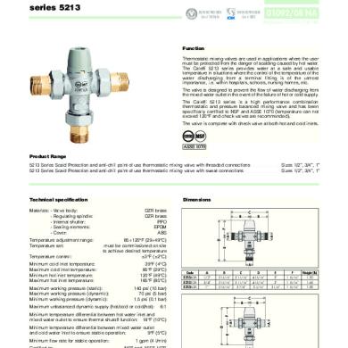
Scald Protection point of use thermostatic mixing valve
CALEFFI
series 5213 RE
D
TERE
G
IS
BSI EN ISO 9001:2000 Cert. n° FM 21654
01092/08 NA
UNI EN ISO 9001:2000 Cert. n° 0003
Replaces 01092/04 NA
Function Thermostatic mixing valves are used in applications where the user must be protected from the danger of scalding caused by hot water. The Caleffi 5213 series provides water at a safe and usable temperature in situations where the control of the temperature of the water discharging from a terminal fitting is of the utmost importance, i.e. within hospitals, schools, nursing homes, etc. The valve is designed to prevent the flow of water discharging from the mixed water outlet in the event of the failure of hot or cold supply. The Caleffi 5213 series is a high performance combination thermostatic and pressure balanced mixing valve and has been specifically certified to NSF and ASSE 1070 (temperature can not exceed 120°F and check valves are recommended). The valve is complete with check valve at both hot and cold inlets.
Product Range 5213 Series Scald Protection and anti-chill point of use thermostatic mixing valve with threaded connections 5213 Series Scald Protection and anti-chill point of use thermostatic mixing valve with sweat connections
Valve body: Regulating spindle: Internal shutter: Sealing elements: Cover:
DZR brass DZR brass PPO EPDM ABS
Temperature adjustment range: Temperature set:
85÷120°F (29÷49°C) must be commissioned on site to achieve desired temperature ±3°F (±2°C)
C B
B
Temperature control:
39°F (4°C) 85°F (29°C) 120°F (49°C) 185°F (85°C)
Minimum cold inlet temperature: Maximum cold inlet temperature: Minimum hot inlet temperature: Maximum hot inlet temperature: Maximum working pressure (static): Maximum working pressure (dynamic): Minimum working pressure (dynamic):
140 psi (10 bar) 70 psi (5 bar) 1.5 psi (0.1 bar)
E
D
A
A
Materials: -
Dimensions
F
Technical specification
Sizes 1/2”, 3/4”, 1” Sizes 1/2”, 3/4”, 1”
A Code 521342A 521352A 521362A
A 1/2” 3/4” 1”
B
C
2 13/16” 2 13/16” 2 15/16”
5 11/16” 5 11/16” 5 7/8”
D 4 15/16” 4 15/16” 5 3/16”
Weight (lb) 1.40 1.55 1.74
F
A
A
Connections:
F 1 15/16” 1 15/16” 1 15/16”
B
D E
Minimum temperature differential between mixed water outlet and cold water inlet to ensure stable operation: 9°F (5°C)
Certified to:
Weight (lb) 1.50 1.65 1.85
6:1
Minimum temperature differential between hot water inlet and mixed water outlet to ensure thermal shutoff function: 18°F (10°C)
Minimum flow rate for stable operation:
3 1/4”
F 1 15/16” 1 15/16” 1 15/16”
C B
Maximum unbalanced dynamic supply (hot/cold or cold/hot):
E 3” 3”
1 gpm (4 l/min) NSF and ASSE 1070
1/2” ÷ 1” NPT male with union 1/2” ÷ 1” sweat with union
A Code 521349A 521359A 521369A
A 1/2” 3/4” 1”
B 2 11/16” 2 7/8” 3 1/8”
C 5 7/16” 5 3/4” 5 5/16”
D 4 5/8” 4 13/16” 5 3/8”
E 2 11/16” 2 15/16” 3 1/4”
Legionella-Pneumophila risk
Temperature - Exposure time °F 170
In systems producing domestic hot water with storage, in order to avoid the dangerous infection known as Legionella, the hot water must be stored at a temperature of at least 140°F. At this temperature it is certain that the growth of the bacteria causing this infection will be totally eliminated. At this temperature, however, the water cannot be used directly. As shown on the diagram opposite, temperatures of more than 120°F can cause burning very quickly. For example, at 130°F partial burning will occurr in approximately 30 seconds, while at 140°F partial burning will occurr in approximately 5 seconds. The time may be reduced by 50 percent or more for children and elderly people.
Total burning 160 150 Partial burning 140 130
Safety condition. Maximum exposure time at a given temperature
120
In view of the above, it is necessary to install a thermostatic mixing valve which can: · reduce the temperature at the point of use to a value lower than that of storage and suitable for sanitary users; · maintain the temperature constant at the point of use when the incoming pressure and temperature conditions vary; · have a thermal shut off function in the event of failure of either hot or cold supply.
110
0,1
1
10
100
1.000
10.000
Seconds
Thermal disinfection The diagram shows the behavior of the bacteria Legionella Pneumophila when the temperature conditions of the water in which it is contained vary. In order to ensure proper thermal “disinfection”, the values must not be below 140°F.
160
Kills bacteria instantly
120
Kills 90% of bacteria in 2 hours
140 100
80 60 32
Exposure time for partial burns
Kills 90% of bacteria in 2 minutes
Temperature
Adult
Children 0÷5 years
Optimum temperature for growth of bacteria
160°F
1s
--
150°F
2s
0.5 s
Surviving bacteria inactive
140°F
5s
1s
130°F
30 s
10 s
120°F
5 min
2.5 min
HOT
A thermostatic mixing valve mixes hot and cold water in such a way as to maintain constant set temperature of the mixed water at the outlet. A thermostatic element is fully immersed into the mixed water. This element then contracts or expands causing movement of the piston, closing either the hot or cold inlets, regulating the flow rates entering the valve. If there are variations of temperature or pressure at the inlets, the internal element automatically reacts to restore the original temperature setting.
COLD
Description of operation
Construction details
Anti-scale materials The material used in the construction of the mixer eliminate the problem of jamming caused by lime deposits. All the working parts are made of a special anti-scale material, with a low friction coefficient, guaranteeing that the performance will be maintained over the long term.
Thermal shutoff In the event of a failure of either the hot or cold supply, the piston will shut off, stopping water discharging from the mixed water outlet. The Caleffi valve requires a minimum temperature differential from hot inlet to mixed water outlet of 18°F (10°C) to ensure the correct operation of the thermal shutoff function.
sweat connections version
MIXED
Flow curves
Temperature adjustment
∆p (psi)
(psi)
20
20
10
10
5 4 3 2
5 4 3 2
1
1
0.5 0.4 0.3 0.2
0.5 0.4 0.3 0.2
0.1
0.1
(bar) 1.0 0.5 0.4 0.3 0.2 0.1 0.05 0.04 0.03 0.02
G (l/min) (gpm)
20
10 50
5
Kv=1.7 (m3/h)
20
1
2 10
Cv= 2
5
0.5 2
0.3
0.01
Temperature setting can be adjusted by removing the cap from the valve body and reversing the cap onto the temperature adjustment spindle. In accordance with the anti-scald requirements, mixed water at the outlet of the sanitary fixtures must not exceed the following values: 120°F (49°C) for domestic or normal buildings 110°F (43,3°C) for hospitals or special buildings 100°F (38°C) for children Temperature setting can then be locked at the desired value using the locking nut.
1
Flow rate-use The Caleffi 5213 series is a thermostatic mixing valve suitable for point of use application. For this reason, the flow rate through the valve is the same as that of the final outlet, e.g. mixer or tap for washbasin, shower or bath. In order to ensure the set temperature, the thermostatic mixing valve must have a minimun flow rate of 1 gpm (4 l/min). The system must be sized taking into account the current legislation with regard to the nominal flow rate of each outlet.
View of temperature adjustment
2
Public buildings, hospitals, schools In these applications, for the type of users of hot water like children, eldery or disabled people, the risk of being scalded is very high. In these installations, the two supply lines of the hot water from the storage and of the cold water can have different origin and work at different pressures. In the event of failure of the cold or hot water supply, the thermostatic mixing valve shuts off the water flow from the outlet, thus avoiding possible scalding or thermal shocks. Installation Before installing a Caleffi Series 5213 mixer, the system must be inspected to ensure that its operating conditions are within the range of the mixer, checking, for example, the supply temperature, supply pressure, etc. Systems where the Caleffi Series 5213 mixer is to be fitted must be drained and cleaned out to remove any dirt or debris which may have accumulated during installation. The installation of filters of appropriate capacity at the inlet of the water from the mains supply is always advisable. Caleffi Series 5213 mixers must be installed by qualified personnel in accordance with the diagrams in this brochure, taking into account all current applicable standards.
Fitting temperature adjustment cap
3
Caleffi Series 5213 mixers can be installed in any position, either vertical or horizontal. The following are shown on the mixer body: - Hot water inlet, marked “H” (Hot). - Cold water inlet, marked “C” (Cold). - Mixed water outlet, marked “MIX”. Temperature adjustment cap in place Check valves In order to prevent undesirable cross flow, check valves should be installed in systems with thermostatic mixing valves. The Caleffi 5213 series is supplied complete with the check valves at the hot and cold inlets.
4
Commissioning In view of the special purpose of the thermostatic mixing valve, it must be commissioned in accordance with current standards by qualified personnel using suitable temperature measuring equipment. Use of a digital thermometer is recommended for measurement of the mixed water temperature.
Locking adjustment spindle with locking nut
Application diagrams Point of use installation
SPECIFICATION SUMMARIES Series 5213 Scald protection point of use thermostatic mixing valve certified to NSF and ASSE 1070. Threaded connections 1/2” (3/4” or 1”) NPT M with union tailpieces. DZR alloy body. Shutter in anti-scale plastic. Seals EPDM. Stainless steel spring. Maximum working temperature 185°F. Setting range 85°F to 120°F. Tolerance ±3°F. Maximum working pressure 140 psi. Maximum supply pressure unbalancing 6:1. Provided with tamper-proof setting lock and check valves at the inlets.
Series 5213 Scald protection point of use thermostatic mixing valve certified to NSF and ASSE 1070. Sweat connections 1/2” (3/4” or 1”) with union tailpieces. DZR alloy body. Shutter in anti-scale plastic. Seals EPDM. Stainless steel spring. Maximum working temperature 185°F. Setting range 85°F to 120°F. Tolerance ±3°F. Maximum working pressure 140 psi. Maximum supply pressure unbalancing 6:1. Provided with tamper-proof setting lock and check valves at the inlets.
We reserve the right to change our products and their relevant technical data, contained in this publication, at any time and without prior notice.
CALEFFI Caleffi North America, Inc.
3883 West Milwaukee Road / Milwaukee, WI 53208 Tel: 414.238.2360 / Fax: 414.238.2366 / www.caleffi.us © Copyright 2008 Caleffi
Related Documents


252-mixing Valve 3cv Solar Caleffi Specification
June 2020 3

