Caleffi 253 Series Solar Safety Relief Valve Specifications
This document was uploaded by user and they confirmed that they have the permission to share it. If you are author or own the copyright of this book, please report to us by using this DMCA report form. Report DMCA
Overview
Download & View Caleffi 253 Series Solar Safety Relief Valve Specifications as PDF for free.
More details
- Words: 772
- Pages: 2
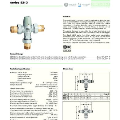
Safety relief valve for solar systems
CALEFFI 253 series
cert. n° 0003
01089/06 GB
ISO 9001
Replaces 01089/03 GB
General The safety relief valves manufactured by Caleffi are produced in compliance with the essential safety requirements laid down by Directive 97/23/EC of the European Parliament and the Council of the European Union for the harmonisation of member States with regard to pressurised equipment. Function
111 5
These safety relief valves are used to control pressure in the primary circuits of solar heating systems. When the calibrated pressure is reached, the valve opens to release the fluid into the atmosphere and prevents the pressure in the system from reaching levels that might damage the solar collectors and equipment installed. These particular series of products have been specially made and certified to work at high temperature with a glycol medium.
Product range 253 series Safety relief valve for solar systems
size 1/2” F x 3/4” F
Technical specifications
Dimensions
Materials: - body: brass EN 12165 CW 617N, chrome plated - control spindle: brass EN 12164 CW614N - obturator seal: high resistance elastomer - spring: stainless UNI 3823 - control knob: PA6G30 Medium: Max. percentage of glycol:
water, glycol solutions 50% PN 10 -30–160°C
Connections:
B
IV TÜV according to SV 100 7.7 N° TÜV 01.SOLAR 02.146.p
C
PED category: Approval:
D
Nominal pressure: Temperature range:
1/2” F x 3/4” F A
Performance Opening overpressure: Closing differential: Discharge capacity: Code Set pressure
253043 3 bar
E
10% 20% 50 kW 253044 4 bar
253046 6 bar
253048 8 bar
253040 10 bar
Code 25304.
A 1/2"
B 3/4"
C 24
D 70
E 33,5
Weight (kg)
0,22
Operating principe The obturator (1), opposed by a set spring (2), raises on reaching the setting pressure and fully opens the outlet. The setting pressure is chosen according to the maximum permissible pressure in the system. The diameter of the outlet connection (3) is greater in order to help discharge the required potential. As the pressure decreases there is the opposite action, with the valve subsequently reclosing within the set tolerances.
2 1 3
Construction details
Discharge pipework The discharge pipework from the safety relief valve must be fitted in such a way as not to prevent the correct operation of the valve and not to cause damage or injury. In accordance with current legislation, the safety relief valve discharge must be visible and carried in suitable collection pipework. The glycol medium must therefore be drained off into a specific container. As shown in the diagram, it is advisable to install a tundish direcly in the discharge pipework.
Application diagram
Temperature and glycol In solar systems, heating fluid of the primary circuit contains glycol as additive and operates at high temperatures; to take account of these particular operating conditions, the obturator seal of safety valve is in high resistance elastomer. The knob is in plastic material especially resistant to increases in temperature and to UV rays, in the case of outdoor installations. Chrome plating The valve body is chrome plated to protect it from the aggression of dirt and moisture, in the case of outdoor installations of solar heating systems. Certification 253 series safety relief valves are certified for specific use in solar heating systems by the certifying body TÜV, in accordance with standard SV 100 Ed. 10.01 par. 7.7. Installation The safety relief valves for solar systems must be installed near the point in the circuit where the system is filled, before expansion vessel. Make sure that there are no shut-off devices between the valve and the rest of the system. The safety relief valves can be fitted vertically or horizontally, but not upside down. This prevents deposits of impurities from affecting correct functioning. The safety relief valves must be installed in line with the flow direction indicated by the arrow on the valve body.
SPECIFICATION SUMMARIES 253 series Safety relief valve for solar heating systems. CE mark as per Directive 97/23/EC. TÜV certified for solar systems. 1/2” F x 3/4” F threaded connections. Brass body. Chrome plated. Diaphragm and obturator seal in high resistance elastomer. Spring in steel UNI 3823. Control knob in PA6G30. Temperature range: -30–160°C. Nominal pressure: PN 10. Calibration setting: 3 bar (3, 4, 6, 8, 10 bar). Medium: water and glycol solutions. Maximum percentage of glycol: 50%.
We reserve the right to change our products and their relevant technical data, contained in this publication, at any time and without prior notice.
CALEFFI CALEFFI S.P.A. · I · 28010 FONTANETO D’AGOGNA (NO) · S.R. 229, N.25 · TEL. +39 0322 8491 R.A. · FAX +39 0322 863723 · Http://www.caleffi.com · E-mail: [email protected] ·
Related Documents


252-mixing Valve 3cv Solar Caleffi Specification
June 2020 3