Materials Notes 15 Rolling - Forging.pdf
This document was uploaded by user and they confirmed that they have the permission to share it. If you are author or own the copyright of this book, please report to us by using this DMCA report form. Report DMCA
Overview
Download & View Materials Notes 15 Rolling - Forging.pdf as PDF for free.
More details
- Words: 2,654
- Pages: 6
Materials & Processes
Online Notes
Rolling & Forging History There are only three ways to make metal products: •
Casting:
•
Powder Metallurgy:
•
Metalworking:
Pouring molten metal into a mold. Compressing powdered metal into a shape, then exposing it to heat and pressure.
Forming, cutting, or joining metal.
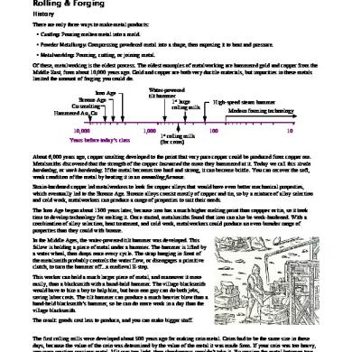
Of these, metalworking is the oldest process. The oldest examples of metalworking are hammered gold and copper from the Middle East, from about 10,000 years ago. Gold and copper are both very ductile materials, but impurities in these metals limited the amount of forging you could do. Iron Age Bronze Age Cu smelting Hammered Au, Cu 10,000 Years before today’s class
Water-powered tilt hammer 1st large rolling mills
1,000
1st rolling mills (for coins)
High-speed steam hammer Modern forming technology 100
10
About 6,000 years ago, copper smelting developed to the point that very pure copper could be produced from copper ore. Metalsmiths discovered that the strength of the copper increased the more they hammered at it. Today we call this strain hardening, or work hardening. If the metal becomes too hard and strong, it can become brittle. You can recover the soft, weak condition of the metal by heating it in an annealing furnace. Strain-hardened copper led metalworkers to look for copper alloys that would have even better mechanical properties, which eventually led to the Bronze Age. Bronze alloys consist mostly of copper and tin, so by a mixture of alloy selection and cold work, metalworkers can produce a range of properties to suit their needs. The Iron Age began about 1300 years later, because iron has a much higher melting point than coppper or tin, so it took time to develop technology for melting it. Once started, metalsmiths found that iron can also be work-hardened. With a combination of alloy selection, heat treatment, and cold work, metalworkers could produce an even broader range of properties than they could with bronze. In the Middle Ages, the water-powered tilt hammer was developed. This fellow is holding a piece of metal under a hammer. The hammer is lifted by a water wheel, then drops once every cycle. The strap hanging in front of the metalsmith probably controls the water flow, or disengages a primitive clutch, to turn the hammer off...a medieval E-stop. This worker can hold a much larger piece of metal, and maneuver it more easily, than a blacksmith with a hand-held hammer. The village blacksmith would have to hire a boy to help him, but here one guy can do both jobs, saving labor costs. The tilt hammer can produce a much heavier blow than a hand-held blacksmith’s hammer, so he can do more work in a day than the village blacksmith. The result: goods cost less to produce, and you can make bigger stuff. The first rolling mills were developed about 500 years ago for making coin metal. Coins had to be the same size in those days, because the value of the coin was determined by the value of the metal it was made from. If your coin was too heavy, you were wasting precious metal. If it was too light, then shopkeepers wouldn’t take it. By passing the metal between two 1
Materials & Processes
Online Notes
rollers, a metalsmith could make a sheet of metal with a uniform thickness in a short time. It took another 200 years before this principle was applied to large mills for rolling steel and iron sheets. Although the Iron Age began more than 3,000 years ago, it wasn’t until these large rolling mills came on-line that iron and steel really became affordable for large structures and machines. In the late 18th / early 19th centuries, steam power was applied to forging. It had the same effect as water power did, 600 years before…it increased productivity, reduced manufacturing costs, and enabled factories to put out large quantities of inexpensive material. Rolling The upper diagram is a side view of the rolling process for manufacturing sheet metal; the lower diagram is a plan view (from the top). Metal starts out with an initial width wo and an initial thickness ho moving at an initial speed of vo. It passes through a pair of rollers, and gets squeezed down to a final thickness hf.
Side view vo
vf hf
ho
Plan view
Bearing block wo
wf
vo
vf
The volume of metal going into the rollers must equal the volume of metal coming out of the rollers. If the width doesn’t change very much, then what happens to the speed of the metal? It goes faster as it comes out of the rollers. Rolled product can be flat and thin (sheet metal), flat and thick (billets), or some other shape (railroad rails; beams shaped like the letter L, T, or H). If the metal contact with the roller is < 1/20th the metal width, we get uniform reduction in thickness with no change in width. This is typical of sheet metal and foil rolling. The diagram shows a crosssection of the sheet metal, as viewed from the end.
End view of thin, wide, flat material ho
Initial cross-section Final cross-section hf wo = w f
2
Materials & Processes
Online Notes
When we roll thick metal, we get uniform reduction in thickness with an increase in width. A large billet of steel will squish out at the edges, as it’s squeezed thinner from top to bottom. When we roll a shape that is not flat, we can get a moderately nonuniform reduction in crosssection. For example, when we roll barstock in an oval cross-section, the thickness change is not uniform in all places. More metal flows at the sides than along the centerline.
End view of thick, flat material
End view of thick, curved material
Initial cross-section
Initial cross-section ho
ho
wo
wo
Final cross-section
Final cross-section hf
When we roll a more complex shape, such as a railroad rail or an I-beam, we can get a highly nonuniform reduction in cross-section.
wf
hf wf
Let’s look at the simplest case: flat rolling of sheet metal. The width doesn’t change; just the thickness and speed change. How fast is the metal moving as it exits the rollers? Let’s say we’re reducing the thickness from 0.050" to 0.040", and the metal going into the rollers is moving at 100 ft./min. The volume V of metal equals the thickness × width × length of the metal, and the volume going in equals the volume coming out, because no metal is created or destroyed in the rolling mill: V o=h o w o L o=h f w f L f =V
Side view vf = ? vo= 100 ft./min. ho= 0.050 in.
f
hf= 0.040 in.
We’ve already learned that with sheet metal, the width doesn’t change, so w o=w f , and the width term drops out: h o L o =h f L f . Rewrite the equation to see that the ratio of the lengths is inversely L f ho proportional to the ratio of the thicknesses: . = Lo h f v f L f /t L f h o = = = . The velocity ratio is inversely proportional to the thickness v o L o /t L o h f ho 0.050 in. ratio. Rewrite the equation to find the final velocity v f =v o =100 fpm =125fpm . When the thickness is hf 0.040 in. reduced 20%, the speed increases 25%. Why would you want to know the exit speed? The metal leaving the rollers will either enter additional rollers for further reduction, or it will be spooled into a coil. A process engineer needs to know the exit speed in order to set up the speed of additional rollers or the takeup reel. The velocity v of the metal = length/time:
Let’s look at a rolling mill on-end. We have two rollers supported by bearing blocks, and a sheet of metal passing between the rollers. In order to reduce the thickness of the sheet metal, we have to apply a force at the bearings. As the force is applied, the rollers bend. Each roller is like a beam problem in Statics or Strength of Materials class…there’s a distributed load which is counteracted by reaction forces at the ends of the beam. When the rollers bend, they’ll look like the cartoons on the right. Of course, the cartoon is exaggerated…the rollers really only bow a few thousandths of an inch, but that’s all it takes to produce metal that doesn’t have a uniform cross-section. We may have started with a rectangular cross-section, but after we send the metal through the rollers, it’s slightly thicker along the centerline, and slightly thinner at the edges.
3
Materials & Processes
Online Notes
Roller Bearing blocks
Let’s think about what this means. The edges of the sheet are getting stretched more than the center. If we were to cut the edges off the sheet, they would be longer than the rest of the sheet. The edges want to be longer, and the center portion wants to be shorter. Now we have residual stresses in the sheet metal. Normally, a coil of metal is too wide to use for a given product, so we have to slit the coil into narrower coils. Let’s look at what happens when we slit this metal along its length. We’re looking at a plan view of the sheet metal, laid out on the floor. At the bottom is a cross-sectional view. The master coil has a crown: it is thicker at the center than it is at the edges.
Slit along the dotted line Plan view of master coil laid flat
The material slit off the right side of the larger coil has a wedgeshaped cross-section. The outer, thinner edge wants to be longer, and the interior wants to be shorter, so the slit material develops camber. You can measure camber by unrolling a coil on the floor, placing a 10-foot ruler along one edge, and measuring the gap between the metal and the ruler. For example: ¼" per 10'.
Camber
10 foot long straightedge
Camber is a big issue in the stamping industry. You feed a coil into a stamping press, and if the dies are relatively long (such as on a progressive die), then a coil with significant camber could get stuck. There are several ways to solve this problem: •
Use rollers that are thicker in the center; as they bend, the resulting sheet metal will be flat.
Plan view of slit coil laid flat
Change the Roller Profle:
•
Support the Rollers:
•
Change the Roller Size:
•
Sell Center Cuts Separately:
End view
End view
Backup rollers can help prevent the main rollers from bending. Larger diameter rollers bend less. Customers will pay more for the center cut (which have no camber) than edge cuts.
Rolled Threads Rolling doesn’t have to produce a smooth surface. You can texture sheet metal by using grit-blasted or knurled rollers. Rolling also doesn’t have to use round rollers and flat sheetmetal. Rolled threads are produced by pressing round rod between grooved dies. The result is a stronger thread, because rolling work-hardens the thread metal. Any inclusions in the metal, that might cause cracks, get rolled parallel to the threads…you don’t move them to the surface by removing material. Rolled threads are better than cut threads for other reasons than strength: 4
Materials & Processes
•
Scrap Reduction:
•
Speed:
•
Quality:
•
Material Cost:
Online Notes
Unlike cut threads, there is no scrap.
Thread rolling is faster than thread cutting. Thread rolling produces a better surface finish. You can use a smaller diameter stock, so raw materials are cheaper.
Forging At the end of World War II, US soldiers came home on troop ships. It took many days, sometimes weeks, to cross the oceans, so one of the things they did to pass the time was take silver quarters and half dollars, and turn them into rings. In those days, quarters and half dollars were made from coin silver, which is 90% silver, 10% copper. It’s a soft, malleable alloy which deforms when you beat on it. If you tap the edge with a spoon, on a long ocean voyage, the diameter will shrink and the rim thickness will increase. The cartoon shows a cross-section through a silver coin across its diameter. You keep tapping to reduce the diameter and thicken the rim. Once the ID is about right, drill it out and file the inside smooth. The photograph shows a ring made from a U.S. silver quarter.
A spoon tapping on a quarter is a pretty small-scale forging operation. In the textbook, there is a photograph of a very large press in Worcester, MA. This press is an ASME landmark; it’s 10 stories tall, one of the largest forges on the planet. Most of the press is underground. When they dug the foundation 100 feet into bedrock, they drained a local lake. The dies weigh up to 50 tons per pair. Why do we forge? •
Minimize Assembly:
•
Eliminate Machining:
•
Strengthening:
You can often manufacture a product by forging a single part instead of by assembling (bolting, welding, etc.) multiple parts. An example is a truck axle shaft, which is a shaft with a disk at one end. An axle shaft can be made by welding a disk onto a shaft, or by upsetting one end of a shaft to make the disk. Imagine the scrap that would be created if we machined axle shafts from solid barstock! Gears are often machined from solid stock, but some gears are forged in the as-finished shape. Forged parts are work-hardened, which can eliminate the need to harden through heat treatment. You can selectively strengthen a component in the area where it’s forged. In contrast, alternative manufacturing processes (machining, casting, and powder metallurgy) do not work-harden the material.
The biggest reason for forging is cost. For some products, forging is cheaper than any other manufacturing method.
In 1871, a fire destroyed 3.3 square miles of Chicago, IL, leaving 100,000 people homeless. 1 Wire nails played a large part in the rapid reconstruction of the city. A wire nail is made by upsetting one end of a wire to produce the nail head. Next, the sharp end is made by cutting a point. Previously, nails were made by cutting them from steel sheet – called cut nails. We still use cut nails for masonry, but wire nails are used for wood because they are cheaper and faster to manufacture. 1
Public-domain image attributed to Nick Bernhard. Original photograph is housed at the Art Institute of Chicago.
5
Materials & Processes
Open-Die Forging Forged parts are made in high volumes with closed dies which form the final shape of the part in one hit of the press. Closed dies are expensive, so low-volume forged parts are often made with open dies (a pair of flat faces, V-dies, or other shapes that form the workpiece). The cartoon at the right illustrates the manufacture of a forged blank that will be cut into a 14 inch diameter gear in a further operation. The first four operations are performed without any tooling; the final operation requires a tapered bolster to form the tapered shaft and large diameter head.
Online Notes
Start with a steel cube
Forge into a shorter, longer brick
Rotate the brick in the forge to flatten the edges and make a cylinder
Bolster
Rotate one end of the cylinder to create a smaller diameter stub
Place the stub-end in a bolster
Forge a flattened, larger diameter head, and taper the stub-end
Dr. Barry Dupen, Indiana University-Purdue University Fort Wayne. Revised April 2015. This document was created with Apache Software Foundation's OpenOffice software v.4.1.0. This work is licensed under Creative Commons Attribution-ShareAlike 4.0 International (CC BY-SA 4.0) See creativecommons.org for license details.
6
Online Notes
Rolling & Forging History There are only three ways to make metal products: •
Casting:
•
Powder Metallurgy:
•
Metalworking:
Pouring molten metal into a mold. Compressing powdered metal into a shape, then exposing it to heat and pressure.
Forming, cutting, or joining metal.
Of these, metalworking is the oldest process. The oldest examples of metalworking are hammered gold and copper from the Middle East, from about 10,000 years ago. Gold and copper are both very ductile materials, but impurities in these metals limited the amount of forging you could do. Iron Age Bronze Age Cu smelting Hammered Au, Cu 10,000 Years before today’s class
Water-powered tilt hammer 1st large rolling mills
1,000
1st rolling mills (for coins)
High-speed steam hammer Modern forming technology 100
10
About 6,000 years ago, copper smelting developed to the point that very pure copper could be produced from copper ore. Metalsmiths discovered that the strength of the copper increased the more they hammered at it. Today we call this strain hardening, or work hardening. If the metal becomes too hard and strong, it can become brittle. You can recover the soft, weak condition of the metal by heating it in an annealing furnace. Strain-hardened copper led metalworkers to look for copper alloys that would have even better mechanical properties, which eventually led to the Bronze Age. Bronze alloys consist mostly of copper and tin, so by a mixture of alloy selection and cold work, metalworkers can produce a range of properties to suit their needs. The Iron Age began about 1300 years later, because iron has a much higher melting point than coppper or tin, so it took time to develop technology for melting it. Once started, metalsmiths found that iron can also be work-hardened. With a combination of alloy selection, heat treatment, and cold work, metalworkers could produce an even broader range of properties than they could with bronze. In the Middle Ages, the water-powered tilt hammer was developed. This fellow is holding a piece of metal under a hammer. The hammer is lifted by a water wheel, then drops once every cycle. The strap hanging in front of the metalsmith probably controls the water flow, or disengages a primitive clutch, to turn the hammer off...a medieval E-stop. This worker can hold a much larger piece of metal, and maneuver it more easily, than a blacksmith with a hand-held hammer. The village blacksmith would have to hire a boy to help him, but here one guy can do both jobs, saving labor costs. The tilt hammer can produce a much heavier blow than a hand-held blacksmith’s hammer, so he can do more work in a day than the village blacksmith. The result: goods cost less to produce, and you can make bigger stuff. The first rolling mills were developed about 500 years ago for making coin metal. Coins had to be the same size in those days, because the value of the coin was determined by the value of the metal it was made from. If your coin was too heavy, you were wasting precious metal. If it was too light, then shopkeepers wouldn’t take it. By passing the metal between two 1
Materials & Processes
Online Notes
rollers, a metalsmith could make a sheet of metal with a uniform thickness in a short time. It took another 200 years before this principle was applied to large mills for rolling steel and iron sheets. Although the Iron Age began more than 3,000 years ago, it wasn’t until these large rolling mills came on-line that iron and steel really became affordable for large structures and machines. In the late 18th / early 19th centuries, steam power was applied to forging. It had the same effect as water power did, 600 years before…it increased productivity, reduced manufacturing costs, and enabled factories to put out large quantities of inexpensive material. Rolling The upper diagram is a side view of the rolling process for manufacturing sheet metal; the lower diagram is a plan view (from the top). Metal starts out with an initial width wo and an initial thickness ho moving at an initial speed of vo. It passes through a pair of rollers, and gets squeezed down to a final thickness hf.
Side view vo
vf hf
ho
Plan view
Bearing block wo
wf
vo
vf
The volume of metal going into the rollers must equal the volume of metal coming out of the rollers. If the width doesn’t change very much, then what happens to the speed of the metal? It goes faster as it comes out of the rollers. Rolled product can be flat and thin (sheet metal), flat and thick (billets), or some other shape (railroad rails; beams shaped like the letter L, T, or H). If the metal contact with the roller is < 1/20th the metal width, we get uniform reduction in thickness with no change in width. This is typical of sheet metal and foil rolling. The diagram shows a crosssection of the sheet metal, as viewed from the end.
End view of thin, wide, flat material ho
Initial cross-section Final cross-section hf wo = w f
2
Materials & Processes
Online Notes
When we roll thick metal, we get uniform reduction in thickness with an increase in width. A large billet of steel will squish out at the edges, as it’s squeezed thinner from top to bottom. When we roll a shape that is not flat, we can get a moderately nonuniform reduction in crosssection. For example, when we roll barstock in an oval cross-section, the thickness change is not uniform in all places. More metal flows at the sides than along the centerline.
End view of thick, flat material
End view of thick, curved material
Initial cross-section
Initial cross-section ho
ho
wo
wo
Final cross-section
Final cross-section hf
When we roll a more complex shape, such as a railroad rail or an I-beam, we can get a highly nonuniform reduction in cross-section.
wf
hf wf
Let’s look at the simplest case: flat rolling of sheet metal. The width doesn’t change; just the thickness and speed change. How fast is the metal moving as it exits the rollers? Let’s say we’re reducing the thickness from 0.050" to 0.040", and the metal going into the rollers is moving at 100 ft./min. The volume V of metal equals the thickness × width × length of the metal, and the volume going in equals the volume coming out, because no metal is created or destroyed in the rolling mill: V o=h o w o L o=h f w f L f =V
Side view vf = ? vo= 100 ft./min. ho= 0.050 in.
f
hf= 0.040 in.
We’ve already learned that with sheet metal, the width doesn’t change, so w o=w f , and the width term drops out: h o L o =h f L f . Rewrite the equation to see that the ratio of the lengths is inversely L f ho proportional to the ratio of the thicknesses: . = Lo h f v f L f /t L f h o = = = . The velocity ratio is inversely proportional to the thickness v o L o /t L o h f ho 0.050 in. ratio. Rewrite the equation to find the final velocity v f =v o =100 fpm =125fpm . When the thickness is hf 0.040 in. reduced 20%, the speed increases 25%. Why would you want to know the exit speed? The metal leaving the rollers will either enter additional rollers for further reduction, or it will be spooled into a coil. A process engineer needs to know the exit speed in order to set up the speed of additional rollers or the takeup reel. The velocity v of the metal = length/time:
Let’s look at a rolling mill on-end. We have two rollers supported by bearing blocks, and a sheet of metal passing between the rollers. In order to reduce the thickness of the sheet metal, we have to apply a force at the bearings. As the force is applied, the rollers bend. Each roller is like a beam problem in Statics or Strength of Materials class…there’s a distributed load which is counteracted by reaction forces at the ends of the beam. When the rollers bend, they’ll look like the cartoons on the right. Of course, the cartoon is exaggerated…the rollers really only bow a few thousandths of an inch, but that’s all it takes to produce metal that doesn’t have a uniform cross-section. We may have started with a rectangular cross-section, but after we send the metal through the rollers, it’s slightly thicker along the centerline, and slightly thinner at the edges.
3
Materials & Processes
Online Notes
Roller Bearing blocks
Let’s think about what this means. The edges of the sheet are getting stretched more than the center. If we were to cut the edges off the sheet, they would be longer than the rest of the sheet. The edges want to be longer, and the center portion wants to be shorter. Now we have residual stresses in the sheet metal. Normally, a coil of metal is too wide to use for a given product, so we have to slit the coil into narrower coils. Let’s look at what happens when we slit this metal along its length. We’re looking at a plan view of the sheet metal, laid out on the floor. At the bottom is a cross-sectional view. The master coil has a crown: it is thicker at the center than it is at the edges.
Slit along the dotted line Plan view of master coil laid flat
The material slit off the right side of the larger coil has a wedgeshaped cross-section. The outer, thinner edge wants to be longer, and the interior wants to be shorter, so the slit material develops camber. You can measure camber by unrolling a coil on the floor, placing a 10-foot ruler along one edge, and measuring the gap between the metal and the ruler. For example: ¼" per 10'.
Camber
10 foot long straightedge
Camber is a big issue in the stamping industry. You feed a coil into a stamping press, and if the dies are relatively long (such as on a progressive die), then a coil with significant camber could get stuck. There are several ways to solve this problem: •
Use rollers that are thicker in the center; as they bend, the resulting sheet metal will be flat.
Plan view of slit coil laid flat
Change the Roller Profle:
•
Support the Rollers:
•
Change the Roller Size:
•
Sell Center Cuts Separately:
End view
End view
Backup rollers can help prevent the main rollers from bending. Larger diameter rollers bend less. Customers will pay more for the center cut (which have no camber) than edge cuts.
Rolled Threads Rolling doesn’t have to produce a smooth surface. You can texture sheet metal by using grit-blasted or knurled rollers. Rolling also doesn’t have to use round rollers and flat sheetmetal. Rolled threads are produced by pressing round rod between grooved dies. The result is a stronger thread, because rolling work-hardens the thread metal. Any inclusions in the metal, that might cause cracks, get rolled parallel to the threads…you don’t move them to the surface by removing material. Rolled threads are better than cut threads for other reasons than strength: 4
Materials & Processes
•
Scrap Reduction:
•
Speed:
•
Quality:
•
Material Cost:
Online Notes
Unlike cut threads, there is no scrap.
Thread rolling is faster than thread cutting. Thread rolling produces a better surface finish. You can use a smaller diameter stock, so raw materials are cheaper.
Forging At the end of World War II, US soldiers came home on troop ships. It took many days, sometimes weeks, to cross the oceans, so one of the things they did to pass the time was take silver quarters and half dollars, and turn them into rings. In those days, quarters and half dollars were made from coin silver, which is 90% silver, 10% copper. It’s a soft, malleable alloy which deforms when you beat on it. If you tap the edge with a spoon, on a long ocean voyage, the diameter will shrink and the rim thickness will increase. The cartoon shows a cross-section through a silver coin across its diameter. You keep tapping to reduce the diameter and thicken the rim. Once the ID is about right, drill it out and file the inside smooth. The photograph shows a ring made from a U.S. silver quarter.
A spoon tapping on a quarter is a pretty small-scale forging operation. In the textbook, there is a photograph of a very large press in Worcester, MA. This press is an ASME landmark; it’s 10 stories tall, one of the largest forges on the planet. Most of the press is underground. When they dug the foundation 100 feet into bedrock, they drained a local lake. The dies weigh up to 50 tons per pair. Why do we forge? •
Minimize Assembly:
•
Eliminate Machining:
•
Strengthening:
You can often manufacture a product by forging a single part instead of by assembling (bolting, welding, etc.) multiple parts. An example is a truck axle shaft, which is a shaft with a disk at one end. An axle shaft can be made by welding a disk onto a shaft, or by upsetting one end of a shaft to make the disk. Imagine the scrap that would be created if we machined axle shafts from solid barstock! Gears are often machined from solid stock, but some gears are forged in the as-finished shape. Forged parts are work-hardened, which can eliminate the need to harden through heat treatment. You can selectively strengthen a component in the area where it’s forged. In contrast, alternative manufacturing processes (machining, casting, and powder metallurgy) do not work-harden the material.
The biggest reason for forging is cost. For some products, forging is cheaper than any other manufacturing method.
In 1871, a fire destroyed 3.3 square miles of Chicago, IL, leaving 100,000 people homeless. 1 Wire nails played a large part in the rapid reconstruction of the city. A wire nail is made by upsetting one end of a wire to produce the nail head. Next, the sharp end is made by cutting a point. Previously, nails were made by cutting them from steel sheet – called cut nails. We still use cut nails for masonry, but wire nails are used for wood because they are cheaper and faster to manufacture. 1
Public-domain image attributed to Nick Bernhard. Original photograph is housed at the Art Institute of Chicago.
5
Materials & Processes
Open-Die Forging Forged parts are made in high volumes with closed dies which form the final shape of the part in one hit of the press. Closed dies are expensive, so low-volume forged parts are often made with open dies (a pair of flat faces, V-dies, or other shapes that form the workpiece). The cartoon at the right illustrates the manufacture of a forged blank that will be cut into a 14 inch diameter gear in a further operation. The first four operations are performed without any tooling; the final operation requires a tapered bolster to form the tapered shaft and large diameter head.
Online Notes
Start with a steel cube
Forge into a shorter, longer brick
Rotate the brick in the forge to flatten the edges and make a cylinder
Bolster
Rotate one end of the cylinder to create a smaller diameter stub
Place the stub-end in a bolster
Forge a flattened, larger diameter head, and taper the stub-end
Dr. Barry Dupen, Indiana University-Purdue University Fort Wayne. Revised April 2015. This document was created with Apache Software Foundation's OpenOffice software v.4.1.0. This work is licensed under Creative Commons Attribution-ShareAlike 4.0 International (CC BY-SA 4.0) See creativecommons.org for license details.
6
Related Documents
Materials Notes 15 Rolling - Forging.pdf
November 2019 8
Materials Notes
October 2019 23
Lecture Notes Of Engineering Materials
June 2020 3
Lecture Notes 15
July 2020 5
Incident Rolling
July 2020 9