Nasa 146685main Srb-et
This document was uploaded by user and they confirmed that they have the permission to share it. If you are author or own the copyright of this book, please report to us by using this DMCA report form. Report DMCA
Overview
Download & View Nasa 146685main Srb-et as PDF for free.
More details
- Words: 6,508
- Pages: 17
!"#" Facts National Aeronautics and Space Administration John F. Kennedy Space Center Kennedy Space Center, Florida 32899
FS-2004-07-012-KSC
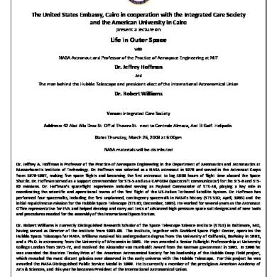
Solid Rocket Boosters and post-launch processing t’s a familiar sight during a Shuttle launch: When the twin Solid Rocket Boosters (SRBs) have expended all their fuel, they jettison away from the orbiter with help from the Booster Separation Motors, about 26.3 nautical miles above the Earth’s surface. They don’t fall immediately because their momentum keeps them traveling upward for about 70 seconds, to approximately 38.6 nautical miles. Then they begin their tumble back toward the ocean. The twin sets of boosters provide 80 percent of the Space Shuttle launch thrust. Each SRB is made up of four “loaded” solid propellant segments called Solid Rocket Motors or SRMs. The SRBs operate parallel with the Space Shuttle main engines for the first two minutes of flight, providing additional thrust needed to escape the gravitational pull of the Earth. The spent SRBs are recovered, cleaned, disassembled, refurbished and reused after each launch. The recovery and clean-
I
ing process, however, is not like driving your car through a car wash. Much of it is dangerous, from diving in the open ocean to handling hazardous materials. To slow the boosters as they begin their descent to the ocean, the nose cap separates at an altitude of 2.5 nautical miles and releases a pilot parachute that, in turn, deploys a drogue chute. This action provides initial deceleration and proper orientation for the SRBs. At 6,000 feet, the frustum is separated when the ordnance system fires the separation ring, located between the frustum and forward skirt structure, containing a linear-shaped charge. The separation pulls out the three main parachutes, providing a “soft” landing in the ocean for the SRBs. Slowing from a speed of 230 miles per hour, they impact at a speed of 51 miles per hour. The entire descent takes about 5 minutes. Because the parachutes provide for a nozzle-first impact, air is trapped in the empty (burned out) motor casing, causing the
booster to float with the forward end approximately 30 feet out of the water. The boosters (with aft skirts still attached), frustums, and parachutes are recovered by two SRB retrieval ships: the Liberty Star and Freedom Star. The nose cap and the aft portion of the exit cone are the only sections left behind. If the nose cap is needed for a special reason, such as post-flight inspection, it will be included in the retrieval process if it can be located. The main parachutes are reeled on board the ship first, followed by the drogue parachutes, which are still attached to the frustum. Once the frustum is about 100 feet from the ship, the parachute lines are reeled in until the frustum can be lifted from the water by a 10-ton crane on board the ship. Recovery of the SRB is the last part of booster retrieval. Divers plug the nozzle of the SRB with an enhanced diver-operated plug, or EDOP. A 2,000foot-long airline attached to the EDOP is plugged into an air compressor located onboard the ship. Air is pumped into the booster and forces all the water out, causing the SRB to topple over into a horizontal position. When the flight hardware is safed, the ships return to Hangar AF at Cape Canaveral Air Force Station (CCAFS), Fla., where the disassembly of the Solid Rocket Boosters will begin. While the SRBs are en route, a 200-ton, Straddle Lift crane at the Hangar is moved into position over the slip, and its lifting slings are dropped into the water. Upon arrival, each ship noses up to a wharf so its SRB can be in line with the hoisting slip. The lead rope is wrapped around an electric capstan that helps
SRB SEGMENTS
to draw the SRB into the slip over the slings. In addition, various technicians surround the SRB and help tow it gently into the slip. In turn, the crane raises each SRB above the water and all remaining saltwater contamination is washed off. While an SRB is being removed from the slip, its frustum and parachutes are offloaded from the ships and placed on transportation platforms. The parachutes will be moved to the Parachute Refurbishment Facility for cleaning and reuse on a future launch. The frustum, however, is moved inside the Hangar AF high bay, where it will undergo assessment and disassembly. When each SRB is ready, it will be moved to a safing area and lowered onto a rail dolly. Technicians then begin the initial safing process. Afterward, the SRB is driven through the wash bay for a cleaning and rinsing, then moved back to the safing area. Ordnance is removed from the forward skirt and the thrust vector control system is depressurized.
Workers at CCAFS help maneuver the SRB into the hoisting sling.
2
Inside, technicians prepare the aft skirts for deservicing. The auxiliary power units are removed, followed by the thrust vector control system and, finally, the aft booster separation motors. The aft skirt is then transported to the Robotic Hydrolase Facility for removal of the TPS. The SRBs are rinsed one more time and then moved inside the Hangar, where they remain for the rest of the disassembly operations. The nozzle, which is the component that helps steer the Shuttle during its first two minutes of flight, is the next item to be removed from the SRBs. Nozzle removal is basically the same as aft skirt removal. Both procedures require the use of a crane and hydraulic panels. The nozzle is pulled straight out and moved over to a transportation platform and placed in the horizontal position. Once again, assessment teams move in to verify damage, if any. The nozzles are placed inside a shipping container and sent to ATK (Alliant Techsystems) in Utah for final processing. The spent case segments are also sent back to Utah for build-up, but they must first be separated from each other. The forward skirt is separated first, followed by the rest of the segments. The pins attaching the segments to each other are removed at the start. Separation rings are then lowered into place. Each ring has three joints that help mold the ring around the segment. The air motor is turned on and the drive mechanism on the front ring
A spent SRB is lifted in a hoisting slip in the Hangar AF area at CCAFS. It will be washed down and moved to the Hangar.
Assessment teams move in to determine if the booster received any damage during flight or postflight activities. Once the SRBs have received a clean bill of health, they are moved into the east and west wash bays. In these bays, they receive the ultimate pressure cleaning – known as “hydrolasing” – that removes the foam, or Thermal Protection System (TPS), from around the tunnel covers, Solid Rocket Motors and aft skirt attach points. Hyrdolasing requires two workers: one to operate the rotating head gun and the other to act as a safety monitor. The gun operates at 15,000 pounds per square inch, producing an extremely loud sound as the water impacts the SRB. Hearing protection is required to work in and around the area. Following hydrolasing operations, the SRB is moved inside the Hangar so that the aft skirts can be removed. Due to the hydrazine still inside the thrust vector control systems, the Hangar is cleared of all non-essential personnel. Once an “all clear” has been established, the aft skirt operations can begin. A separation ring is placed on the SRB to ready the aft skirt for demating. Technicians operate hydraulic control panels that are connected by lines to the separation rings. As hydraulic fluid flows through the lines, the aft skirt is forced away from the aft segment. Next, the crane trolley backs up, clearing the aft skirt away from the SRB. The aft skirt is then rotated and lowered onto blocks, lifted and placed on a transportation dolly, and moved inside the Thrust Vector Control Deservicing Facility for hydrazine removal and additional disassembly operations.
After retrieval post-launch, an SRB is processed through the washing station at Hangar AF.
3
rotates, causing the four jack screws to turn and press against the pads on the second ring. This forces the front segment to move slightly away from the back segment. Technicians help finish the job by pushing the rail car forward. Because of the impact when the boosters fall into the ocean, all internal segment debris ends up in the forward segments. This type of debris is rinsed out into special carts and taken away. Assessment teams make one last check before the segments are placed on flatbed trucks. The individual segments are transferred to a railhead located on the launch side at Kennedy Space Center. Upon arrival, a segment is moved underneath a 60-ton crane that lifts it off the flatbed. A train backs up and the segment is lowered onto a rail car. Yellow transportation covers are placed over each segment and secured. The covered segments are moved to J and J Railroad, where they will be hooked up to yet another train for the long trip back to Utah. Meanwhile, work at the Hangar continues. The remaining light hardware – the frustum, forward skirt and aft skirt – must be refurbished. All three pieces go through the same procedures following disassembly: hydrolasing to remove the TPS and media blasting to remove paint coatings, as well as the application of alodine, primer, paint and sealants. Let’s follow the frustum through the sequence. The frustum was offloaded from the retrieval ship and moved inside the Hangar AF High Bay for disassembly. Various parts, such as the flotation curtains and foam blocks, now are removed. Some parts, like the barometric switch tubes, are sent to “Small Parts,” an area inside the Hangar. Robotic hydrolasing is used to remove TPS from the exterior surface of the frustum. The frustum is placed on a Mobile Access Refurbishment Stand, or MARS, and moved inside the Robotic Hydrolase Facility. The robot moves into position and the MARS begins to rotate on a turntable. After one complete rotation, the robot moves up slightly, removing TPS materials from the next portion of the frustum. The robot continues in this fashion until it reaches the top of the hardware. Putting the larger pieces of hardware through this process removes the majority of the TPS, topcoat, 4
(Left) The segment is in the West Wash area at Hangar AF, CCAFS, on a rail car dolly prior to SRB Aft Skirt demating. Residual aft skirt foam can be seen.
(Far left) Workers at Hangar AF, CCAFS, examine an aft section of an empty SRB.
(Below) At Hangar AF, CCAFS, a technician cleans an area around the field joint of one of the SRBs recovered after a launch.
(Below, far left) The railroad engine transports SRB segments (in yellow containers) to Utah. The segments will be prepared for a future launch and returned to KSC.
5
At CCAFS, the frustum of a forward skirt assembly from a spent SRB is removed from the retrieval ship. It will be moved inside Hangar AF High Bay for disassembly.
structure surface, it “burns,” or leaves an etching behind. A second technician follows, rinsing off any excessive residue, which flows down into a special drain. The leftover alodine will be picked up by a hazardous materials group for disposal. Using a system much like a shop vacuum, the excessive water is removed from the frustum before it is moved next door to a paint and primer booth. Technicians mix the primer and paint and apply both to the larger pieces, both inside and out, using spray guns attached to a roll-around canister. The primer is applied the first day, with the topcoat usually done the following day. After the paint has cured, the frustum moves to a large work area across from the paint booth, where sealant is applied. Sealant is mixed with a catalyst to create a moisture-resistant material for certain areas of the vehicle where water intrusion is not desired. Later, the frustum, aft skirt and forward skirt will be moved to the Assembly and Refurbishment Facility for final assembly build-up and testing. All of these post-flight procedures are repeated after each mission.
primer and black sealant. The stripped-down frustum is now transported to a base support contractor, where it is blasted with a plastic media to remove remnants of the protective finish. The plastic bead blast strips the frustum down to bare metal, preparing it for the next stage of processing: a water break test and alodine application. The frustum undergoes extensive inspection, nondestructive evaluation, and repair procedures before the application of protective finishes. To help the frustum maintain a protective coating of alodine, the entire surface must be clean. The water break test determines the success of the bead blasting. As water is sprayed over the frustum, technicians watch for trouble spots. The water must flow down in sheets. If it beads up, then the frustum is not clean in certain areas and requires further cleaning by hand. After the frustum has passed the water break test, alodine is applied. The brownish liquid is used as a preventive measure for corrosion control and is handled as a hazardous material. The technician fills a large container with the alodine and moves around the frustum while spraying. As the alodine hits the
6
Mission Event
Elapsed Time After Liftoff
Speed Height (miles/kilometers (feet/meters) per hour)
Booster separation from Shuttle
124 seconds
156,000 feet (47,549 meters)
Apogee (maximum height booster reaches after separation)
196 seconds
238,000 feet (72,542 meters)
Nose cap separation/pilot chute deploy
349 seconds
16,000 feet (4,877 meters)
Drogue chute deploy
350 seconds
15,530 feet (4,734 meters)
Frustum separation/main chute deploy
371 seconds
6,450 feet (1,966 meters)
Booster impact and main chute separation
414 seconds
50 mph (81 kph)
Frustum/drogue chute impact
459 seconds
40 mph (64 kph)
360 mph (579 kph)
250 mph (402 kph)
A Solid Rocket Booster Retrieval Ship has arrived on scene after splashdown of an SRB segment following a Space Shuttle launch. The segment floats vertically until divers can insert an Enhanced Diver-Operated Plug (EDOP) into the nozzle of the booster. The EDOP pumps air into the empty casing until all water is expelled and it falls horizontally and can be towed back to port.
7
Captions, front page: (Top) The Solid Rocket Boosters on Space Shuttle Discovery spew a column of flame as it races toward space on mission STS-105 to the International Space Station. The twin sets of boosters provide 80 percent of the Space Shuttle launch thrust. Approximately 2 minutes after launch, the boosters will be jettisoned into the Atlantic Ocean and recovered for future use.
(Middle) The SRB Retrieval Ship Liberty Star maneuvers a spent booster toward the Hangar AF wharf at CCAFS so its SRB can be in line with the hoisting slip. A 200-ton, Straddle Lift crane lifts the booster above the water and all remaining saltwater contamination is washed off.
(Bottom) The individual segments are transferred to a railhead located on the launch side at Kennedy Space Center. A train backs up and the segment is lowered onto a rail car. Yellow transportation covers are placed over each segment and secured. The covered segments are moved to J and J Railroad, where they are hooked up to yet another train for the long trip back to Utah.
National Aeronautics and Space Administration
John F. Kennedy Space Center Kennedy Space Center, Florida 32899
FS-2004-07-012-KSC
NASA Facts National Aeronautics and Space Administration Marshall Space Flight Center Huntsville, Alabama 35812
FS-2004-08-97-MSFC
August 2004
External Tank Return to Flight Focus Area
Thermal Protection System NASA’s Space Shuttle Program has initiated an aggressive program to minimize any debris that could be produced by the Space Shuttle’s elements: the Orbiter, the External Tank, the Solid Rocket Boosters and the Main Engines. The Shuttle’s External Tank Project Office has completed a top-to-bottom assessment of the tank’s Thermal Protection System and has examined all areas where the tank’s foam insulation, a component of the Thermal Protection System, is prone to loss.
Because the tank is not retrievable, engineers must rely on testing, computer analysis, and video and photographic imaging to determine if there is a possibility of debris created during launch and ascent. These tests and analyses help determine the potential for foam loss and the possible ways to improve the overall safety of the External Tank.
External Tank Thermal Protection System
The project office is also investigating new techniques that will allow the foam to be inspected for internal defects without damaging it. The initial focus is on manually sprayed closeout, or final, foam applications. Although they are not yet fully developed, non-destructive evaluation techniques like backscatter radiography and terahertz imaging could offer an additional level of verification for the foam. Backscatter radiography involves inspection of a part by detecting the X-rays that are scattered back from the part when it is illuminated with an X-ray source. It was originally developed for military use at the University of Florida in Gainesville, Fla. Terahertz imaging is a relatively new technology based on the terahertz (THz) range of the electromagnetic spectrum. A defect will cause the wave to reflect back to the receiver. The main advantage of a terahertz imager is that it does not emit any radiation, capturing pictures of the natural terahertz rays emitted by almost all objects. Occupying a portion of the spectrum between infrared and microwaves, from 1011 to 1013 Hertz, terahertz waves can pass easily through some solid materials, like walls and clothes, and can also be focused as light to create images of objects. The terahertz imaging is being developed in conjunction with NASA’s Langley Research Center in Langley, Va. In addition to developing new nondestructive evaluation (NDE) techniques, the Project Office has created a stringent process control system to ensure that all newly-applied foam meets NASA specifications.
The new process controls include the institution of high fidelity mockups, video recording of processes, simplification of application design, acquisition of all process parameter data and the institution of detailed spray instructions. FOAM FACTS The Space Shuttle's External Tank is covered with spray-on foam insulation that serves to insulate the tank before and during launch. The foam is one of two components in the External Tank's Thermal Protection System, or TPS. There are two basic Thermal Protection Systems on the External Tank: One is low-density, closed-cell foam. The other Thermal Protection System component is a denser composite material called ablator, made of silicone resins and cork. An ablator is a material that dissipates heat by eroding. The closed-cell foam used on the tank acreage is a Spray-On-Foam-Insulation often referred to by its acronym as SOFI (pronounced so -FEE). The composite material is Super Lightweight Ablator, known as SLA (pronounced slaw). The External Tank uses ablators on areas that are subjected to extreme heat, such as the aft dome near the engine exhaust and on protuberances that are exposed to aerodynamic heating, such as the cable trays. The closed-cell foam used on the tank was developed to keep the propellants that fuel the Shuttle's three Main Engines at optimum temperature. It keeps the Shuttle's liquid hydrogen fuel at minus 423 degrees Fahrenheit and the liquid oxygen tank at minus 297 degrees Fahrenheit -- even as the tank sits under
the hot Florida sun -- while preventing a buildup of ice on the outside of the tank. The foam insulation must also be durable enough to endure a 180-day stay at the launch pad, withstand temperatures up to 115 degrees Fahrenheit, humidity as high as 100 percent, and resist sand, salt, fog, rain, solar radiation and even fungus. Then, during launch, the foam must tolerate temperatures as high as 1,200 degrees Fahrenheit generated by aerodynamic friction and rocket exhaust. Finally, when the External Tank returns to Earth and begins reentry into the atmosphere -- about 30 minutes after launch -- the foam helps hold the tank together even as temperatures and tank pressurization inside work to break up the tank, allowing it to safely disintegrate over a remote ocean location. Though the foam insulation on the majority of the tank is only 1-inch thick, it adds 4,823 pounds to the tank's weight. Insulation on the liquid hydrogen tank is somewhat thicker -- between 1.5 to 2 inches thick. Though the foam's density varies with the type, an average density is about 2.4 pounds per cubic foot. The average NCFI – NCFI is an acronym for North Carolina Foam Industries-- density is 2.27 pounds per cubic foot. The tank's foam is polyurethane-type foam composed of five primary ingredients: polymeric isocyanate, a flame retardant, a surfactant, a blowing agent, and a catalyst. A surfactant controls the surface tension of a liquid and thus cell formation. The blowing agent – originally CFC 11-creates the foam's cellular structure by making millions of tiny bubbles or foam cells. Application of the foam, whether automated by computer or hand-sprayed,
is designed to meet NASA's requirements for finish, thickness, roughness, density, strength and adhesion. As in most assembly production situations, the foam is applied in specially designed, environmentally controlled spray cells and sprayed in several phases, often over a period of several weeks. Prior to spraying, the foam's raw material and mechanical properties are tested to assure it meets NASA specifications. Multiple visual inspections of all foam surfaces are also performed after the spraying is complete. Most of the foam is applied at Lockheed Martin's Michoud Assembly Facility in New Orleans when the tank is manufactured, including most of the "closeout" areas, or final areas applied. These closeouts are done either by hand pouring or manually spraying. Some additional close-outs are completed once the tank reaches Kennedy Space Center in Cape Canaveral, Fla. There are four specially engineered closed-cell foams used on the tank. The larger sections of the tank are covered in NCFI 24-124, which accounts for 77 percent of the total foam used on the tank. NCFI 24-57, which has a slightly different formulation than NCFI 24-124, is used on the aft dome, or bottom, of the liquid hydrogen tank. PDL 1034, hand-poured foam used for filling odd-shaped cavities, and BX 250/265 foam is used on the tank's "closeout" areas. During the early days of the External Tank's development, PDL was an acronym for Product Development Laboratory, the first supplier of that foam. NCFI 24-124 and NCFI 24-57 are mechanically sprayed foams; BX 250/265 is manually-applied, or hand-sprayed.
Environmental Protection Agency In 1987, the United States and 45 other nations adopted the "Montreal Protocol on Substances that Deplete the Ozone Layer." Under the Protocol, class I ozone depleting compounds, such as Chlorofluorocarbon 11 known as CFC 11 -- the Freon-based blowing agent used in the production of the External Tank's foam -- was to be phased out of production by the end of 1995. Production of these compounds after 1995 is allowed only by "Essential Use Exemption" and must have Montreal Protocol approval. After extensive testing the External Tank Project proposed hydro chlorofluorocarbon HCFC 141b as the CFC 11 replacement. HCFC 141b is a blowing agent more environmental regulation compliant. At the same time, the Environmental Protection Agency allowed the External Tank program to continue use of stockpiled supplies of CFC 11until HCFC 141b was certified for use on the Space Shuttle and phased in. However, in 1999, the EPA proposed to expand its regulations by implementing a ban on nonessential products that release
class I ozone-depleting substances under section 610 of the Clean Air Act. Under the proposed rule, sale and distribution of BX 250, used to insulate part of the External Tank, would have been banned because it contains CFC 11. NASA asked the EPA to revise the proposed rule to provide an exemption for BX 250 and other foam containing CFC 11 used in applications associated with space vehicles. The EPA allowed the exemption but limited it to the Thermal Protection System of the Shuttle's External Tank and only allowed the use of CFC 11 as a blowing agent when no other chlorofluorocarbons are used in the foam product. The "new" foam containing HCFC 141b was first used on the liquid hydrogen tank aft dome of ET-82 and flew on STS-79 in 1996. The foam was implemented on the tank's acreage, or its larger portions, beginning with ET-88, which flew on STS86 in 1997. In December 2001, BX-265, which contains HCFC 141b, first flew as a replacement of BX-250. However BX250 continued to be flown as BX-265 was implemented step wise through the manufacturing process.
NASA Facts National Aeronautics and Space Administration Marshall Space Flight Center Huntsville, Alabama 35812
FS-2004-08-95-MSFC
August 2004
External Tank Return to Flight Focus Area
Forward Bipod Fitting When the Space Shuttle returns to flight, the External Tank will have a redesigned forward bipod fitting – a design that meets the recommendation of the Columbia Accident Investigation Board to minimize potential debris by eliminating the large insulating foam bipod ramps. The new design eliminates these ramps in favor of electric heaters. The insulating foam ramps were in place to prevent ice buildup – another potential debris source -- on the tank’s bipod fittings. Each external tank has two bipod fittings that connect the tank to the Orbiter through the Shuttle's two forward attachment struts.
Bipod Location
Bipod ramp, as flown
History The External Tank Project Office began developing bipod redesign concepts after insulating foam from the left bipod ramp area came off during the October 2002 launch of Space Shuttle Atlantis on the STS-112 mission. During the launch of Columbia on its STS-107 mission in January 2003, a similar loss prompted NASA's Office of Space Flight to mandate a redesign of the bipod ramp before the Shuttle fleet could return to flight. The bipod ramps were wedgeshaped foam structures, approximately 30 inches long, 14 inches wide and 12 inches tall. The ramps were applied by hand spraying BX250/265 foam over the bipod fittings during the final stages of the tank's preparation. The final ramp shapes were created by hand carving the foam to required dimensions.
Dissection of existing bipod ramps on tanks in inventory conducted during the STS-107 investigation indicated that hand-spraying over the complex geometry of the fittings was prone to produce internal voids and defects. These internal voids and defects have been shown to contribute to foam loss during ascent.
Bipod Redesign
Design Changes The bipod redesign will allow the fittings to fly mainly exposed --minus the insulating foam ramps. The fittings themselves are the same basic design as before. However, to prevent ice formation while the shuttle sits on the launch pad loaded with extremely cold cryogenic liquid hydrogen fuel, the redesign adds four rod heaters placed below each fitting in a new copper plate. The copper plate with heaters is sandwiched between the fitting and an existing phenolic thermal isolating pad. This thermal isolator helps to reduce heat loss from the copper plate into the extremely cold liquid hydrogen tank. The heaters are cartridge-type heaters with a wire coil inserted into a tube filled with magnesium oxide. They are 0.25 inches in diameter and 5 inches in length. Each heater can produce up
to 300 watts of power when operated at 120 volts AC. The heaters will only function pre-launch, and will be powered and monitored through connections in the Ground Umbilical Carrier Plate, which separates when the shuttle is launched. The control of the heaters will be through groundbased Programmable Logic Controllers that will vary the heater power based on temperature sensors co-located with the heaters at the copper plates. Additional temperature sensors on the bipod fittings will monitor the fitting temperatures to ensure they stay well above freezing. To minimize the potential for a launch scrub, the heaters and temperature sensors have built-in redundancy to permit successful operation even in the presence of certain hardware failures. Other Fitting Modifications Although the original bipod fittings were covered with insulating foam ramps, the bipod spindles, which connected the fittings to the struts, remained exposed. These spindles were required to rotate to accommodate the shrinkage of the tank that occurs when it becomes extremely cold. These spindles each contained a heater element, and it will no longer be required. Elimination of the spindle heaters meant a smaller end cover could be used on the fitting. Since the fittings will now fly exposed to the aerodynamic heating environment, the end covers will get much hotter during flight and to withstand higher temperatures will now be made from Inconel 718. The fittings themselves are made from Titanium and are already capable of withstanding these higher temperatures.
The new design also requires additional cabling to operate the heating system. It includes eight circuits – four for each bipod – that run from the External Tank Ground Umbilical Carrier Plate to the heaters under the bipod fitting. The new design is an alternative derived from three original redesign options proposed by the project office to the Space Shuttle Program Requirements Change Board on May 9, 2003, and later presented by the Columbia Accident Investigation Board to the public. Testing Testing is an important factor in any redesign or modification because it validates the integrity of the design. Though testing cannot duplicate actual flight, it can significantly reduce risk because it allows for careful observation and precise control over the test article. The new bipod fitting design has undergone wind tunnel tests, structural tests, and thermal tests, during both its design and implementation phases, to certify it is ready for flight. These tests ensure the new design does not affect the current External Tank loads and stresses. Structural testing performed at NASA's Michoud Assembly Facility in New Orleans demonstrated the load capability – its ability to withstand external forces acting on the structure -of the redesigned fitting. The structural testing included both the effects of cryogenic -- subzero -- temperatures at the fitting mounting area and the high temperature effects of aerodynamic heating of the fitting itself.
Thermal testing performed at Eglin Air Force Base, Fla., demonstrated the capability of the heater system to prevent ice or frost formation on the launch pad. These thermal tests encompassed all tanking and detanking scenarios, and the environmental chamber at Eglin permitted all possible environmental conditions (extreme combinations of temperatures, humidity, and winds) to be examined. Wind tunnel testing performed at Arnold Engineering Development Center at Arnold Air Force Base, Tenn., demonstrated the design's aerodynamic capabilities and its ability to resist aerodynamic loads and high temperatures generated during ascent. Although most of the foam that covered the bipod area has been eliminated with the redesign, the base area must still be covered with hand-sprayed foam. To ensure that this foam is free from internal defects that could cause foam loss during flight, the foam application techniques for this area have been refined and thoroughly tested through a process Verification and Validation program. Implementation The bipod redesign will be retrofitted on the eight existing tanks and implemented on all new tanks. Lockheed Martin Space Systems will do the work at NASA's Michoud Assembly Facility in New Orleans. Delivery of the first retrofitted tank to the Kennedy Space Center in Cape Canaveral, Fla., is expected in October 2004.
NASA Facts National Aeronautics and Space Administration Marshall Space Flight Center Huntsville, Alabama 35812
FS-2003-09-112-MSFC
September 2003
Improvements to the Space Shuttle’s External Tank As NASA prepares to return the Space Shuttle to flight, the Shuttle’s External Tank Project Office is assessing the design of the tank’s Thermal Protection System, or TPS, and examining any areas where the tank’s foam insulation, a component of the tank’s Thermal Protection System, has the potential to be lost. The focus of this effort is to minimize any debris the tank could potentially generate, and is one of the recommendations made by the Columbia Accident Investigation Board following the loss of the Space Shuttle Columbia and her crew. The External Tank is the "fuel tank" for the Shuttle’s Orbiter; it contains the propellants used by the Shuttle’s Main Engines. It is also the only component of the Space Shuttle that is not reused. Approximately 8.5 minutes into a Shuttle flight the tank – its propellant used -- is jettisoned and disintegrates over a remote part of the ocean. Because the tank is not retrievable, NASA’s engineers are unable to confirm by inspection how the tank’s insulation performed during ascent. Instead, they must rely on testing, computer analysis and video and photographic imaging to determine if there is a possibility of foam shedding during launch. The External Tank Project Office is re-evaluating the tank’s thermal protection and the potential for debris, through testing and analysis of some of its components, including areas that could be prone to foam loss such the protuberance airload ramps and the liquid hydrogen tank/intertank flange closeout area and an area that is prone to ice, the liquid oxygen feedline bellows. These tests and analyses are expected to determine the potential for foam loss in these areas and possible ways to improve the overall safety of the External Tank for the Space Shuttle system.
The project office is also reviewing how the thermal protection system is applied to the tank and examining new techniques that will allow the foam to be tested without damaging it. Liquid oxygen feedline bellows The liquid oxygen feedline bellows is part of the liquid oxygen feedline assembly that extends externally along the right side of the liquid hydrogen tank, up to and within the intertank, which joins the liquid hydrogen and oxygen tanks, and then to the aft dome, or bottom, of the liquid oxygen tank. The line is approximately 70 feet long and about 17 inches in diameter. The three liquid oxygen feedline bellows are joints that allow the feedline to move, or flex, when the tank is assembled and during installation of the feedline. The joints also allow the lines to adjust as the liquid hydrogen tank is filled and permit the line to adapt to the forces generated at liftoff. The feedline is insulated with foam. However, because the bellows must allow for movement, they are not insulated. The current configuration of the bellows allows ice to form during prelaunch tanking of the External Tank when moisture in the outside air contacts the cold surface of the uninsulated bellows; because the bellows are not insulated, they are subjected to the minus 423 degree temperature of the liquid hydrogen tank. Though there have been no reported losses of foam insulation from this area of the tank, photographs taken prior to launch indicate that ice does form. If ice in this area dislodged during liftoff, it could potentially damage the Shuttle system. Therefore, the project office is redesigning the bellows to eliminate the potential for ice debris and will retrofit the new design to the External Tank. Design concepts under consideration are a flexible heated bellows boot, or protective covering; use of
heated gaseous nitrogen (GN2) or gaseous helium (GHe) to purge the bellows prior to launch; and incorporating along with the use of a coating material that sheds water. These concepts are intended to either prevent ice formation on the bellows or to contain the ice during ascent.
Protuberance Airload Ramps, or PAL Ramps The External Tank’s protuberance airload ramps, known as PAL ramps, are foam ramps designed to reduce adverse aerodynamic loading, or forces, on the tank’s cable trays and its pressurization lines during launch. One of those ramps is near the top of the liquid oxygen tank, close to the nose cone; the other is below the intertank, near the top of the liquid hydrogen tank. Presently, the three redesign options being evaluated are eliminating the ramps, reducing the size of the ramps to “mini” ramps, or building a “fence” to protect the cable trays and lines. The project office will continue to evaluate the redesign candidates and, after completing a comprehensive testing and analysis program on the options, select one for implementation. Liquid Hydrogen Tank/ Intertank Flange The External Tank’s intertank is the structural connection that joins the liquid hydrogen tank and the liquid oxygen tank. Flanges, which are joints that function like a tab or a seam on a shirt, are affixed at the top and bottom of the intertank so the two tanks can be attached to the intertank. The liquid hydrogen tank flange is at the bottom of the intertank. Once the two tanks are joined to the intertank, the flange is insulated with foam. There is a history of foam loss from this area during liftoff -- foam divots, or pieces, from this area have typically been less than 0.100 pound and considered a maintenance issue for the Orbiter. Therefore, the External Tank Project Office is conducting tests to determine why foam insulation in this area sheds. One modification being considered is to continually purge the intertank flange crevice with heated gaseous nitrogen or helium to prevent the formation of liquid nitrogen in the joint area of the LH2 tank to intertank. Although not proven, this is considered a possible contributor to foam loss. Another modification under consideration is to enhance or
improve the foam application procedures on the flange area. TPS (Foam) Verification and Nondestructive Inspection of Foam In response to the Columbia Accident Investigation findings, the External Tank Project Office is also reassessing how the foam is both manually applied and hand-sprayed, on the tank. Using flight history, the project office has created a list of areas where such applications could later generate debris and is establishing requirements for additional quality tests for these applications. Included with this assessment is a review and update of the process controls, such as requiring at least two employees attend all critical hand-spraying applications to ensure proper processing and security. NASA is also pursuing the development of nondestructive inspection techniques on the tank’s thermal protection system. The initial focus is on manually sprayed closeout, or final, foam applications. The project office is surveying state-ofthe-art technologies and evaluating their capabilities. Initially, test articles with known defects -- such as voids in the foam -- were used to determine the detection limits of the various methods. Two technologies that show promise are terahertz imaging and backscatter radiography. The main advantage of a terahertz imager is that it does not emit any radiation, capturing pictures of the natural terahertz rays emitted by almost all objects. Occupying a portion of the spectrum between infrared and microwaves, from 10¹¹ to 10¹³ Hertz, terahertz waves can pass easily through some solid materials, like walls and clothes, and can also be focused as light to create images of objects. The terahertz imaging is being developed in conjunction with NASA’s Langley Research Center in Langley, Va. Backscatter radiography was originally developed for military use at the University of Florida in Gainesville, Fla. The backscatter technique uses Xray photons that bounce off the electrons of materials. The External Tank Project Office is conducting more comprehensive testing on these technologies.
FS-2004-07-012-KSC
Solid Rocket Boosters and post-launch processing t’s a familiar sight during a Shuttle launch: When the twin Solid Rocket Boosters (SRBs) have expended all their fuel, they jettison away from the orbiter with help from the Booster Separation Motors, about 26.3 nautical miles above the Earth’s surface. They don’t fall immediately because their momentum keeps them traveling upward for about 70 seconds, to approximately 38.6 nautical miles. Then they begin their tumble back toward the ocean. The twin sets of boosters provide 80 percent of the Space Shuttle launch thrust. Each SRB is made up of four “loaded” solid propellant segments called Solid Rocket Motors or SRMs. The SRBs operate parallel with the Space Shuttle main engines for the first two minutes of flight, providing additional thrust needed to escape the gravitational pull of the Earth. The spent SRBs are recovered, cleaned, disassembled, refurbished and reused after each launch. The recovery and clean-
I
ing process, however, is not like driving your car through a car wash. Much of it is dangerous, from diving in the open ocean to handling hazardous materials. To slow the boosters as they begin their descent to the ocean, the nose cap separates at an altitude of 2.5 nautical miles and releases a pilot parachute that, in turn, deploys a drogue chute. This action provides initial deceleration and proper orientation for the SRBs. At 6,000 feet, the frustum is separated when the ordnance system fires the separation ring, located between the frustum and forward skirt structure, containing a linear-shaped charge. The separation pulls out the three main parachutes, providing a “soft” landing in the ocean for the SRBs. Slowing from a speed of 230 miles per hour, they impact at a speed of 51 miles per hour. The entire descent takes about 5 minutes. Because the parachutes provide for a nozzle-first impact, air is trapped in the empty (burned out) motor casing, causing the
booster to float with the forward end approximately 30 feet out of the water. The boosters (with aft skirts still attached), frustums, and parachutes are recovered by two SRB retrieval ships: the Liberty Star and Freedom Star. The nose cap and the aft portion of the exit cone are the only sections left behind. If the nose cap is needed for a special reason, such as post-flight inspection, it will be included in the retrieval process if it can be located. The main parachutes are reeled on board the ship first, followed by the drogue parachutes, which are still attached to the frustum. Once the frustum is about 100 feet from the ship, the parachute lines are reeled in until the frustum can be lifted from the water by a 10-ton crane on board the ship. Recovery of the SRB is the last part of booster retrieval. Divers plug the nozzle of the SRB with an enhanced diver-operated plug, or EDOP. A 2,000foot-long airline attached to the EDOP is plugged into an air compressor located onboard the ship. Air is pumped into the booster and forces all the water out, causing the SRB to topple over into a horizontal position. When the flight hardware is safed, the ships return to Hangar AF at Cape Canaveral Air Force Station (CCAFS), Fla., where the disassembly of the Solid Rocket Boosters will begin. While the SRBs are en route, a 200-ton, Straddle Lift crane at the Hangar is moved into position over the slip, and its lifting slings are dropped into the water. Upon arrival, each ship noses up to a wharf so its SRB can be in line with the hoisting slip. The lead rope is wrapped around an electric capstan that helps
SRB SEGMENTS
to draw the SRB into the slip over the slings. In addition, various technicians surround the SRB and help tow it gently into the slip. In turn, the crane raises each SRB above the water and all remaining saltwater contamination is washed off. While an SRB is being removed from the slip, its frustum and parachutes are offloaded from the ships and placed on transportation platforms. The parachutes will be moved to the Parachute Refurbishment Facility for cleaning and reuse on a future launch. The frustum, however, is moved inside the Hangar AF high bay, where it will undergo assessment and disassembly. When each SRB is ready, it will be moved to a safing area and lowered onto a rail dolly. Technicians then begin the initial safing process. Afterward, the SRB is driven through the wash bay for a cleaning and rinsing, then moved back to the safing area. Ordnance is removed from the forward skirt and the thrust vector control system is depressurized.
Workers at CCAFS help maneuver the SRB into the hoisting sling.
2
Inside, technicians prepare the aft skirts for deservicing. The auxiliary power units are removed, followed by the thrust vector control system and, finally, the aft booster separation motors. The aft skirt is then transported to the Robotic Hydrolase Facility for removal of the TPS. The SRBs are rinsed one more time and then moved inside the Hangar, where they remain for the rest of the disassembly operations. The nozzle, which is the component that helps steer the Shuttle during its first two minutes of flight, is the next item to be removed from the SRBs. Nozzle removal is basically the same as aft skirt removal. Both procedures require the use of a crane and hydraulic panels. The nozzle is pulled straight out and moved over to a transportation platform and placed in the horizontal position. Once again, assessment teams move in to verify damage, if any. The nozzles are placed inside a shipping container and sent to ATK (Alliant Techsystems) in Utah for final processing. The spent case segments are also sent back to Utah for build-up, but they must first be separated from each other. The forward skirt is separated first, followed by the rest of the segments. The pins attaching the segments to each other are removed at the start. Separation rings are then lowered into place. Each ring has three joints that help mold the ring around the segment. The air motor is turned on and the drive mechanism on the front ring
A spent SRB is lifted in a hoisting slip in the Hangar AF area at CCAFS. It will be washed down and moved to the Hangar.
Assessment teams move in to determine if the booster received any damage during flight or postflight activities. Once the SRBs have received a clean bill of health, they are moved into the east and west wash bays. In these bays, they receive the ultimate pressure cleaning – known as “hydrolasing” – that removes the foam, or Thermal Protection System (TPS), from around the tunnel covers, Solid Rocket Motors and aft skirt attach points. Hyrdolasing requires two workers: one to operate the rotating head gun and the other to act as a safety monitor. The gun operates at 15,000 pounds per square inch, producing an extremely loud sound as the water impacts the SRB. Hearing protection is required to work in and around the area. Following hydrolasing operations, the SRB is moved inside the Hangar so that the aft skirts can be removed. Due to the hydrazine still inside the thrust vector control systems, the Hangar is cleared of all non-essential personnel. Once an “all clear” has been established, the aft skirt operations can begin. A separation ring is placed on the SRB to ready the aft skirt for demating. Technicians operate hydraulic control panels that are connected by lines to the separation rings. As hydraulic fluid flows through the lines, the aft skirt is forced away from the aft segment. Next, the crane trolley backs up, clearing the aft skirt away from the SRB. The aft skirt is then rotated and lowered onto blocks, lifted and placed on a transportation dolly, and moved inside the Thrust Vector Control Deservicing Facility for hydrazine removal and additional disassembly operations.
After retrieval post-launch, an SRB is processed through the washing station at Hangar AF.
3
rotates, causing the four jack screws to turn and press against the pads on the second ring. This forces the front segment to move slightly away from the back segment. Technicians help finish the job by pushing the rail car forward. Because of the impact when the boosters fall into the ocean, all internal segment debris ends up in the forward segments. This type of debris is rinsed out into special carts and taken away. Assessment teams make one last check before the segments are placed on flatbed trucks. The individual segments are transferred to a railhead located on the launch side at Kennedy Space Center. Upon arrival, a segment is moved underneath a 60-ton crane that lifts it off the flatbed. A train backs up and the segment is lowered onto a rail car. Yellow transportation covers are placed over each segment and secured. The covered segments are moved to J and J Railroad, where they will be hooked up to yet another train for the long trip back to Utah. Meanwhile, work at the Hangar continues. The remaining light hardware – the frustum, forward skirt and aft skirt – must be refurbished. All three pieces go through the same procedures following disassembly: hydrolasing to remove the TPS and media blasting to remove paint coatings, as well as the application of alodine, primer, paint and sealants. Let’s follow the frustum through the sequence. The frustum was offloaded from the retrieval ship and moved inside the Hangar AF High Bay for disassembly. Various parts, such as the flotation curtains and foam blocks, now are removed. Some parts, like the barometric switch tubes, are sent to “Small Parts,” an area inside the Hangar. Robotic hydrolasing is used to remove TPS from the exterior surface of the frustum. The frustum is placed on a Mobile Access Refurbishment Stand, or MARS, and moved inside the Robotic Hydrolase Facility. The robot moves into position and the MARS begins to rotate on a turntable. After one complete rotation, the robot moves up slightly, removing TPS materials from the next portion of the frustum. The robot continues in this fashion until it reaches the top of the hardware. Putting the larger pieces of hardware through this process removes the majority of the TPS, topcoat, 4
(Left) The segment is in the West Wash area at Hangar AF, CCAFS, on a rail car dolly prior to SRB Aft Skirt demating. Residual aft skirt foam can be seen.
(Far left) Workers at Hangar AF, CCAFS, examine an aft section of an empty SRB.
(Below) At Hangar AF, CCAFS, a technician cleans an area around the field joint of one of the SRBs recovered after a launch.
(Below, far left) The railroad engine transports SRB segments (in yellow containers) to Utah. The segments will be prepared for a future launch and returned to KSC.
5
At CCAFS, the frustum of a forward skirt assembly from a spent SRB is removed from the retrieval ship. It will be moved inside Hangar AF High Bay for disassembly.
structure surface, it “burns,” or leaves an etching behind. A second technician follows, rinsing off any excessive residue, which flows down into a special drain. The leftover alodine will be picked up by a hazardous materials group for disposal. Using a system much like a shop vacuum, the excessive water is removed from the frustum before it is moved next door to a paint and primer booth. Technicians mix the primer and paint and apply both to the larger pieces, both inside and out, using spray guns attached to a roll-around canister. The primer is applied the first day, with the topcoat usually done the following day. After the paint has cured, the frustum moves to a large work area across from the paint booth, where sealant is applied. Sealant is mixed with a catalyst to create a moisture-resistant material for certain areas of the vehicle where water intrusion is not desired. Later, the frustum, aft skirt and forward skirt will be moved to the Assembly and Refurbishment Facility for final assembly build-up and testing. All of these post-flight procedures are repeated after each mission.
primer and black sealant. The stripped-down frustum is now transported to a base support contractor, where it is blasted with a plastic media to remove remnants of the protective finish. The plastic bead blast strips the frustum down to bare metal, preparing it for the next stage of processing: a water break test and alodine application. The frustum undergoes extensive inspection, nondestructive evaluation, and repair procedures before the application of protective finishes. To help the frustum maintain a protective coating of alodine, the entire surface must be clean. The water break test determines the success of the bead blasting. As water is sprayed over the frustum, technicians watch for trouble spots. The water must flow down in sheets. If it beads up, then the frustum is not clean in certain areas and requires further cleaning by hand. After the frustum has passed the water break test, alodine is applied. The brownish liquid is used as a preventive measure for corrosion control and is handled as a hazardous material. The technician fills a large container with the alodine and moves around the frustum while spraying. As the alodine hits the
6
Mission Event
Elapsed Time After Liftoff
Speed Height (miles/kilometers (feet/meters) per hour)
Booster separation from Shuttle
124 seconds
156,000 feet (47,549 meters)
Apogee (maximum height booster reaches after separation)
196 seconds
238,000 feet (72,542 meters)
Nose cap separation/pilot chute deploy
349 seconds
16,000 feet (4,877 meters)
Drogue chute deploy
350 seconds
15,530 feet (4,734 meters)
Frustum separation/main chute deploy
371 seconds
6,450 feet (1,966 meters)
Booster impact and main chute separation
414 seconds
50 mph (81 kph)
Frustum/drogue chute impact
459 seconds
40 mph (64 kph)
360 mph (579 kph)
250 mph (402 kph)
A Solid Rocket Booster Retrieval Ship has arrived on scene after splashdown of an SRB segment following a Space Shuttle launch. The segment floats vertically until divers can insert an Enhanced Diver-Operated Plug (EDOP) into the nozzle of the booster. The EDOP pumps air into the empty casing until all water is expelled and it falls horizontally and can be towed back to port.
7
Captions, front page: (Top) The Solid Rocket Boosters on Space Shuttle Discovery spew a column of flame as it races toward space on mission STS-105 to the International Space Station. The twin sets of boosters provide 80 percent of the Space Shuttle launch thrust. Approximately 2 minutes after launch, the boosters will be jettisoned into the Atlantic Ocean and recovered for future use.
(Middle) The SRB Retrieval Ship Liberty Star maneuvers a spent booster toward the Hangar AF wharf at CCAFS so its SRB can be in line with the hoisting slip. A 200-ton, Straddle Lift crane lifts the booster above the water and all remaining saltwater contamination is washed off.
(Bottom) The individual segments are transferred to a railhead located on the launch side at Kennedy Space Center. A train backs up and the segment is lowered onto a rail car. Yellow transportation covers are placed over each segment and secured. The covered segments are moved to J and J Railroad, where they are hooked up to yet another train for the long trip back to Utah.
National Aeronautics and Space Administration
John F. Kennedy Space Center Kennedy Space Center, Florida 32899
FS-2004-07-012-KSC
NASA Facts National Aeronautics and Space Administration Marshall Space Flight Center Huntsville, Alabama 35812
FS-2004-08-97-MSFC
August 2004
External Tank Return to Flight Focus Area
Thermal Protection System NASA’s Space Shuttle Program has initiated an aggressive program to minimize any debris that could be produced by the Space Shuttle’s elements: the Orbiter, the External Tank, the Solid Rocket Boosters and the Main Engines. The Shuttle’s External Tank Project Office has completed a top-to-bottom assessment of the tank’s Thermal Protection System and has examined all areas where the tank’s foam insulation, a component of the Thermal Protection System, is prone to loss.
Because the tank is not retrievable, engineers must rely on testing, computer analysis, and video and photographic imaging to determine if there is a possibility of debris created during launch and ascent. These tests and analyses help determine the potential for foam loss and the possible ways to improve the overall safety of the External Tank.
External Tank Thermal Protection System
The project office is also investigating new techniques that will allow the foam to be inspected for internal defects without damaging it. The initial focus is on manually sprayed closeout, or final, foam applications. Although they are not yet fully developed, non-destructive evaluation techniques like backscatter radiography and terahertz imaging could offer an additional level of verification for the foam. Backscatter radiography involves inspection of a part by detecting the X-rays that are scattered back from the part when it is illuminated with an X-ray source. It was originally developed for military use at the University of Florida in Gainesville, Fla. Terahertz imaging is a relatively new technology based on the terahertz (THz) range of the electromagnetic spectrum. A defect will cause the wave to reflect back to the receiver. The main advantage of a terahertz imager is that it does not emit any radiation, capturing pictures of the natural terahertz rays emitted by almost all objects. Occupying a portion of the spectrum between infrared and microwaves, from 1011 to 1013 Hertz, terahertz waves can pass easily through some solid materials, like walls and clothes, and can also be focused as light to create images of objects. The terahertz imaging is being developed in conjunction with NASA’s Langley Research Center in Langley, Va. In addition to developing new nondestructive evaluation (NDE) techniques, the Project Office has created a stringent process control system to ensure that all newly-applied foam meets NASA specifications.
The new process controls include the institution of high fidelity mockups, video recording of processes, simplification of application design, acquisition of all process parameter data and the institution of detailed spray instructions. FOAM FACTS The Space Shuttle's External Tank is covered with spray-on foam insulation that serves to insulate the tank before and during launch. The foam is one of two components in the External Tank's Thermal Protection System, or TPS. There are two basic Thermal Protection Systems on the External Tank: One is low-density, closed-cell foam. The other Thermal Protection System component is a denser composite material called ablator, made of silicone resins and cork. An ablator is a material that dissipates heat by eroding. The closed-cell foam used on the tank acreage is a Spray-On-Foam-Insulation often referred to by its acronym as SOFI (pronounced so -FEE). The composite material is Super Lightweight Ablator, known as SLA (pronounced slaw). The External Tank uses ablators on areas that are subjected to extreme heat, such as the aft dome near the engine exhaust and on protuberances that are exposed to aerodynamic heating, such as the cable trays. The closed-cell foam used on the tank was developed to keep the propellants that fuel the Shuttle's three Main Engines at optimum temperature. It keeps the Shuttle's liquid hydrogen fuel at minus 423 degrees Fahrenheit and the liquid oxygen tank at minus 297 degrees Fahrenheit -- even as the tank sits under
the hot Florida sun -- while preventing a buildup of ice on the outside of the tank. The foam insulation must also be durable enough to endure a 180-day stay at the launch pad, withstand temperatures up to 115 degrees Fahrenheit, humidity as high as 100 percent, and resist sand, salt, fog, rain, solar radiation and even fungus. Then, during launch, the foam must tolerate temperatures as high as 1,200 degrees Fahrenheit generated by aerodynamic friction and rocket exhaust. Finally, when the External Tank returns to Earth and begins reentry into the atmosphere -- about 30 minutes after launch -- the foam helps hold the tank together even as temperatures and tank pressurization inside work to break up the tank, allowing it to safely disintegrate over a remote ocean location. Though the foam insulation on the majority of the tank is only 1-inch thick, it adds 4,823 pounds to the tank's weight. Insulation on the liquid hydrogen tank is somewhat thicker -- between 1.5 to 2 inches thick. Though the foam's density varies with the type, an average density is about 2.4 pounds per cubic foot. The average NCFI – NCFI is an acronym for North Carolina Foam Industries-- density is 2.27 pounds per cubic foot. The tank's foam is polyurethane-type foam composed of five primary ingredients: polymeric isocyanate, a flame retardant, a surfactant, a blowing agent, and a catalyst. A surfactant controls the surface tension of a liquid and thus cell formation. The blowing agent – originally CFC 11-creates the foam's cellular structure by making millions of tiny bubbles or foam cells. Application of the foam, whether automated by computer or hand-sprayed,
is designed to meet NASA's requirements for finish, thickness, roughness, density, strength and adhesion. As in most assembly production situations, the foam is applied in specially designed, environmentally controlled spray cells and sprayed in several phases, often over a period of several weeks. Prior to spraying, the foam's raw material and mechanical properties are tested to assure it meets NASA specifications. Multiple visual inspections of all foam surfaces are also performed after the spraying is complete. Most of the foam is applied at Lockheed Martin's Michoud Assembly Facility in New Orleans when the tank is manufactured, including most of the "closeout" areas, or final areas applied. These closeouts are done either by hand pouring or manually spraying. Some additional close-outs are completed once the tank reaches Kennedy Space Center in Cape Canaveral, Fla. There are four specially engineered closed-cell foams used on the tank. The larger sections of the tank are covered in NCFI 24-124, which accounts for 77 percent of the total foam used on the tank. NCFI 24-57, which has a slightly different formulation than NCFI 24-124, is used on the aft dome, or bottom, of the liquid hydrogen tank. PDL 1034, hand-poured foam used for filling odd-shaped cavities, and BX 250/265 foam is used on the tank's "closeout" areas. During the early days of the External Tank's development, PDL was an acronym for Product Development Laboratory, the first supplier of that foam. NCFI 24-124 and NCFI 24-57 are mechanically sprayed foams; BX 250/265 is manually-applied, or hand-sprayed.
Environmental Protection Agency In 1987, the United States and 45 other nations adopted the "Montreal Protocol on Substances that Deplete the Ozone Layer." Under the Protocol, class I ozone depleting compounds, such as Chlorofluorocarbon 11 known as CFC 11 -- the Freon-based blowing agent used in the production of the External Tank's foam -- was to be phased out of production by the end of 1995. Production of these compounds after 1995 is allowed only by "Essential Use Exemption" and must have Montreal Protocol approval. After extensive testing the External Tank Project proposed hydro chlorofluorocarbon HCFC 141b as the CFC 11 replacement. HCFC 141b is a blowing agent more environmental regulation compliant. At the same time, the Environmental Protection Agency allowed the External Tank program to continue use of stockpiled supplies of CFC 11until HCFC 141b was certified for use on the Space Shuttle and phased in. However, in 1999, the EPA proposed to expand its regulations by implementing a ban on nonessential products that release
class I ozone-depleting substances under section 610 of the Clean Air Act. Under the proposed rule, sale and distribution of BX 250, used to insulate part of the External Tank, would have been banned because it contains CFC 11. NASA asked the EPA to revise the proposed rule to provide an exemption for BX 250 and other foam containing CFC 11 used in applications associated with space vehicles. The EPA allowed the exemption but limited it to the Thermal Protection System of the Shuttle's External Tank and only allowed the use of CFC 11 as a blowing agent when no other chlorofluorocarbons are used in the foam product. The "new" foam containing HCFC 141b was first used on the liquid hydrogen tank aft dome of ET-82 and flew on STS-79 in 1996. The foam was implemented on the tank's acreage, or its larger portions, beginning with ET-88, which flew on STS86 in 1997. In December 2001, BX-265, which contains HCFC 141b, first flew as a replacement of BX-250. However BX250 continued to be flown as BX-265 was implemented step wise through the manufacturing process.
NASA Facts National Aeronautics and Space Administration Marshall Space Flight Center Huntsville, Alabama 35812
FS-2004-08-95-MSFC
August 2004
External Tank Return to Flight Focus Area
Forward Bipod Fitting When the Space Shuttle returns to flight, the External Tank will have a redesigned forward bipod fitting – a design that meets the recommendation of the Columbia Accident Investigation Board to minimize potential debris by eliminating the large insulating foam bipod ramps. The new design eliminates these ramps in favor of electric heaters. The insulating foam ramps were in place to prevent ice buildup – another potential debris source -- on the tank’s bipod fittings. Each external tank has two bipod fittings that connect the tank to the Orbiter through the Shuttle's two forward attachment struts.
Bipod Location
Bipod ramp, as flown
History The External Tank Project Office began developing bipod redesign concepts after insulating foam from the left bipod ramp area came off during the October 2002 launch of Space Shuttle Atlantis on the STS-112 mission. During the launch of Columbia on its STS-107 mission in January 2003, a similar loss prompted NASA's Office of Space Flight to mandate a redesign of the bipod ramp before the Shuttle fleet could return to flight. The bipod ramps were wedgeshaped foam structures, approximately 30 inches long, 14 inches wide and 12 inches tall. The ramps were applied by hand spraying BX250/265 foam over the bipod fittings during the final stages of the tank's preparation. The final ramp shapes were created by hand carving the foam to required dimensions.
Dissection of existing bipod ramps on tanks in inventory conducted during the STS-107 investigation indicated that hand-spraying over the complex geometry of the fittings was prone to produce internal voids and defects. These internal voids and defects have been shown to contribute to foam loss during ascent.
Bipod Redesign
Design Changes The bipod redesign will allow the fittings to fly mainly exposed --minus the insulating foam ramps. The fittings themselves are the same basic design as before. However, to prevent ice formation while the shuttle sits on the launch pad loaded with extremely cold cryogenic liquid hydrogen fuel, the redesign adds four rod heaters placed below each fitting in a new copper plate. The copper plate with heaters is sandwiched between the fitting and an existing phenolic thermal isolating pad. This thermal isolator helps to reduce heat loss from the copper plate into the extremely cold liquid hydrogen tank. The heaters are cartridge-type heaters with a wire coil inserted into a tube filled with magnesium oxide. They are 0.25 inches in diameter and 5 inches in length. Each heater can produce up
to 300 watts of power when operated at 120 volts AC. The heaters will only function pre-launch, and will be powered and monitored through connections in the Ground Umbilical Carrier Plate, which separates when the shuttle is launched. The control of the heaters will be through groundbased Programmable Logic Controllers that will vary the heater power based on temperature sensors co-located with the heaters at the copper plates. Additional temperature sensors on the bipod fittings will monitor the fitting temperatures to ensure they stay well above freezing. To minimize the potential for a launch scrub, the heaters and temperature sensors have built-in redundancy to permit successful operation even in the presence of certain hardware failures. Other Fitting Modifications Although the original bipod fittings were covered with insulating foam ramps, the bipod spindles, which connected the fittings to the struts, remained exposed. These spindles were required to rotate to accommodate the shrinkage of the tank that occurs when it becomes extremely cold. These spindles each contained a heater element, and it will no longer be required. Elimination of the spindle heaters meant a smaller end cover could be used on the fitting. Since the fittings will now fly exposed to the aerodynamic heating environment, the end covers will get much hotter during flight and to withstand higher temperatures will now be made from Inconel 718. The fittings themselves are made from Titanium and are already capable of withstanding these higher temperatures.
The new design also requires additional cabling to operate the heating system. It includes eight circuits – four for each bipod – that run from the External Tank Ground Umbilical Carrier Plate to the heaters under the bipod fitting. The new design is an alternative derived from three original redesign options proposed by the project office to the Space Shuttle Program Requirements Change Board on May 9, 2003, and later presented by the Columbia Accident Investigation Board to the public. Testing Testing is an important factor in any redesign or modification because it validates the integrity of the design. Though testing cannot duplicate actual flight, it can significantly reduce risk because it allows for careful observation and precise control over the test article. The new bipod fitting design has undergone wind tunnel tests, structural tests, and thermal tests, during both its design and implementation phases, to certify it is ready for flight. These tests ensure the new design does not affect the current External Tank loads and stresses. Structural testing performed at NASA's Michoud Assembly Facility in New Orleans demonstrated the load capability – its ability to withstand external forces acting on the structure -of the redesigned fitting. The structural testing included both the effects of cryogenic -- subzero -- temperatures at the fitting mounting area and the high temperature effects of aerodynamic heating of the fitting itself.
Thermal testing performed at Eglin Air Force Base, Fla., demonstrated the capability of the heater system to prevent ice or frost formation on the launch pad. These thermal tests encompassed all tanking and detanking scenarios, and the environmental chamber at Eglin permitted all possible environmental conditions (extreme combinations of temperatures, humidity, and winds) to be examined. Wind tunnel testing performed at Arnold Engineering Development Center at Arnold Air Force Base, Tenn., demonstrated the design's aerodynamic capabilities and its ability to resist aerodynamic loads and high temperatures generated during ascent. Although most of the foam that covered the bipod area has been eliminated with the redesign, the base area must still be covered with hand-sprayed foam. To ensure that this foam is free from internal defects that could cause foam loss during flight, the foam application techniques for this area have been refined and thoroughly tested through a process Verification and Validation program. Implementation The bipod redesign will be retrofitted on the eight existing tanks and implemented on all new tanks. Lockheed Martin Space Systems will do the work at NASA's Michoud Assembly Facility in New Orleans. Delivery of the first retrofitted tank to the Kennedy Space Center in Cape Canaveral, Fla., is expected in October 2004.
NASA Facts National Aeronautics and Space Administration Marshall Space Flight Center Huntsville, Alabama 35812
FS-2003-09-112-MSFC
September 2003
Improvements to the Space Shuttle’s External Tank As NASA prepares to return the Space Shuttle to flight, the Shuttle’s External Tank Project Office is assessing the design of the tank’s Thermal Protection System, or TPS, and examining any areas where the tank’s foam insulation, a component of the tank’s Thermal Protection System, has the potential to be lost. The focus of this effort is to minimize any debris the tank could potentially generate, and is one of the recommendations made by the Columbia Accident Investigation Board following the loss of the Space Shuttle Columbia and her crew. The External Tank is the "fuel tank" for the Shuttle’s Orbiter; it contains the propellants used by the Shuttle’s Main Engines. It is also the only component of the Space Shuttle that is not reused. Approximately 8.5 minutes into a Shuttle flight the tank – its propellant used -- is jettisoned and disintegrates over a remote part of the ocean. Because the tank is not retrievable, NASA’s engineers are unable to confirm by inspection how the tank’s insulation performed during ascent. Instead, they must rely on testing, computer analysis and video and photographic imaging to determine if there is a possibility of foam shedding during launch. The External Tank Project Office is re-evaluating the tank’s thermal protection and the potential for debris, through testing and analysis of some of its components, including areas that could be prone to foam loss such the protuberance airload ramps and the liquid hydrogen tank/intertank flange closeout area and an area that is prone to ice, the liquid oxygen feedline bellows. These tests and analyses are expected to determine the potential for foam loss in these areas and possible ways to improve the overall safety of the External Tank for the Space Shuttle system.
The project office is also reviewing how the thermal protection system is applied to the tank and examining new techniques that will allow the foam to be tested without damaging it. Liquid oxygen feedline bellows The liquid oxygen feedline bellows is part of the liquid oxygen feedline assembly that extends externally along the right side of the liquid hydrogen tank, up to and within the intertank, which joins the liquid hydrogen and oxygen tanks, and then to the aft dome, or bottom, of the liquid oxygen tank. The line is approximately 70 feet long and about 17 inches in diameter. The three liquid oxygen feedline bellows are joints that allow the feedline to move, or flex, when the tank is assembled and during installation of the feedline. The joints also allow the lines to adjust as the liquid hydrogen tank is filled and permit the line to adapt to the forces generated at liftoff. The feedline is insulated with foam. However, because the bellows must allow for movement, they are not insulated. The current configuration of the bellows allows ice to form during prelaunch tanking of the External Tank when moisture in the outside air contacts the cold surface of the uninsulated bellows; because the bellows are not insulated, they are subjected to the minus 423 degree temperature of the liquid hydrogen tank. Though there have been no reported losses of foam insulation from this area of the tank, photographs taken prior to launch indicate that ice does form. If ice in this area dislodged during liftoff, it could potentially damage the Shuttle system. Therefore, the project office is redesigning the bellows to eliminate the potential for ice debris and will retrofit the new design to the External Tank. Design concepts under consideration are a flexible heated bellows boot, or protective covering; use of
heated gaseous nitrogen (GN2) or gaseous helium (GHe) to purge the bellows prior to launch; and incorporating along with the use of a coating material that sheds water. These concepts are intended to either prevent ice formation on the bellows or to contain the ice during ascent.
Protuberance Airload Ramps, or PAL Ramps The External Tank’s protuberance airload ramps, known as PAL ramps, are foam ramps designed to reduce adverse aerodynamic loading, or forces, on the tank’s cable trays and its pressurization lines during launch. One of those ramps is near the top of the liquid oxygen tank, close to the nose cone; the other is below the intertank, near the top of the liquid hydrogen tank. Presently, the three redesign options being evaluated are eliminating the ramps, reducing the size of the ramps to “mini” ramps, or building a “fence” to protect the cable trays and lines. The project office will continue to evaluate the redesign candidates and, after completing a comprehensive testing and analysis program on the options, select one for implementation. Liquid Hydrogen Tank/ Intertank Flange The External Tank’s intertank is the structural connection that joins the liquid hydrogen tank and the liquid oxygen tank. Flanges, which are joints that function like a tab or a seam on a shirt, are affixed at the top and bottom of the intertank so the two tanks can be attached to the intertank. The liquid hydrogen tank flange is at the bottom of the intertank. Once the two tanks are joined to the intertank, the flange is insulated with foam. There is a history of foam loss from this area during liftoff -- foam divots, or pieces, from this area have typically been less than 0.100 pound and considered a maintenance issue for the Orbiter. Therefore, the External Tank Project Office is conducting tests to determine why foam insulation in this area sheds. One modification being considered is to continually purge the intertank flange crevice with heated gaseous nitrogen or helium to prevent the formation of liquid nitrogen in the joint area of the LH2 tank to intertank. Although not proven, this is considered a possible contributor to foam loss. Another modification under consideration is to enhance or
improve the foam application procedures on the flange area. TPS (Foam) Verification and Nondestructive Inspection of Foam In response to the Columbia Accident Investigation findings, the External Tank Project Office is also reassessing how the foam is both manually applied and hand-sprayed, on the tank. Using flight history, the project office has created a list of areas where such applications could later generate debris and is establishing requirements for additional quality tests for these applications. Included with this assessment is a review and update of the process controls, such as requiring at least two employees attend all critical hand-spraying applications to ensure proper processing and security. NASA is also pursuing the development of nondestructive inspection techniques on the tank’s thermal protection system. The initial focus is on manually sprayed closeout, or final, foam applications. The project office is surveying state-ofthe-art technologies and evaluating their capabilities. Initially, test articles with known defects -- such as voids in the foam -- were used to determine the detection limits of the various methods. Two technologies that show promise are terahertz imaging and backscatter radiography. The main advantage of a terahertz imager is that it does not emit any radiation, capturing pictures of the natural terahertz rays emitted by almost all objects. Occupying a portion of the spectrum between infrared and microwaves, from 10¹¹ to 10¹³ Hertz, terahertz waves can pass easily through some solid materials, like walls and clothes, and can also be focused as light to create images of objects. The terahertz imaging is being developed in conjunction with NASA’s Langley Research Center in Langley, Va. Backscatter radiography was originally developed for military use at the University of Florida in Gainesville, Fla. The backscatter technique uses Xray photons that bounce off the electrons of materials. The External Tank Project Office is conducting more comprehensive testing on these technologies.