Instrumentation Amplifier
This document was uploaded by user and they confirmed that they have the permission to share it. If you are author or own the copyright of this book, please report to us by using this DMCA report form. Report DMCA
Overview
Download & View Instrumentation Amplifier as PDF for free.
More details
- Words: 702
- Pages: 2
Instrumentation amplifier From Wikipedia, the free encyclopedia Jump to: navigation, search This page is about the electronic device. Amplifiers for musical instruments are instrument amplifiers.
Typical instrumentation amplifier schematic An instrumentation (or instrumentational) amplifier is a type of differential amplifier that has been outfitted with input buffers, which eliminate the need for input impedance matching and thus make the amplifier particularly suitable for use in measurement and test equipment. Additional characteristics include very low DC offset, low drift, low noise, very high open-loop gain, very high common-mode rejection ratio, and very high input impedances. Instrumentation amplifiers are used where great accuracy and stability of the circuit both short- and long-term are required. Although the instrumentation amplifier is usually shown schematically identical to a standard opamp, the electronic instrumentation amp is almost always internally composed of 3 op-amps. These are arranged so that there is one op-amp to buffer each input (+,−), and one to produce the desired output with adequate impedance matching for the function.[1][2] The most commonly used instrumentation amplifier circuit is shown in the figure. The gain of the circuit is
The rightmost amplifier, along with the resistors labelled R2 and R3 is just the standard differential amplifier circuit, with gain = R3 / R2 and differential input resistance = 2·R2. The two amplifiers on the left are the buffers. With Rgain removed (open circuited), they are simple unity
gain buffers; the circuit will work in that state, with gain simply equal to R3 / R2 and high input impedance because of the buffers. The buffer gain could be increased by putting resistors between the buffer inverting inputs and ground to shunt away some of the negative feedback; however, the single resistor Rgain between the two inverting inputs is a much more elegant method: it increases the differential-mode gain of the buffer pair while leaving the commonmode gain equal to 1. This increases the common-mode rejection ratio (CMRR) of the circuit and also enables the buffers to handle much larger common-mode signals without clipping than would be the case if they were separate and had the same gain. Another benefit of the method is that it boosts the gain using a single resistor rather than a pair, thus avoiding a resistor-matching problem (although the two R1s need to be matched), and very conveniently allowing the gain of the circuit to be changed by changing the value of a single resistor. A set of switch-selectable resistors or even a potentiometer can be used for Rgain, providing easy changes to the gain of the circuit, without the complexity of having to switch matched pairs of resistors. The ideal common-mode gain of an instrumentation amplifier is zero. In the circuit shown, common-mode gain is caused by mismatches in the values of the equally-numbered resistors and by the mis-match in common mode gains of the two input op-amps. Obtaining very closely matched resistors is a significant difficulty in fabricating these circuits, as is optimizing the common mode performance of the input op-amps.[3] An instrumentation amp can also be built with 2 op-amps to save on cost and increase CMRR, but the gain must be higher than 2 (+6 dB).[4][5] Instrumentation amplifiers can be built with individual op-amps and precision resistors, but are also available in integrated circuit form from several manufacturers (including Texas Instruments, National Semiconductor, Analog Devices, Linear Technology and Maxim Integrated Products). An IC instrumentation amplifier typically contains closely matched lasertrimmed resistors, and therefore offers excellent common-mode rejection. Examples include AD620, MAX4194 and INA128. Instrumentation Amplifiers can also be designed using "Indirect Current-feedback Architecture", which extend the operating range of these amplifiers to the negative power supply rail, and in some cases the positive power supply rail. This can be particularly useful in single-supply systems, where the negative power rail is simply the circuit ground (GND). Examples of parts utilizing this architecture are MAX4208/MAX4209 and AD8129/AD8130. Feedback-free instrumentation amplifier is the high input impedance diferential amplifier designed without the external feedback network. This allows reduction in the number of amplifiers (one instead of three), reduced noise (no thermal noise is brought on by the feedback resistors) and increased bandwidth (no frequency compensation is needed). The design of such amplifiers is treated here.
Related Documents

Instrumentation Amplifier
December 2019 18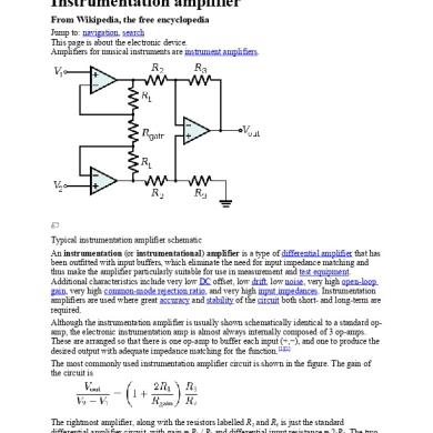
Instrumentation Amplifier
July 2020 8
Opamp And Instrumentation Amplifier
October 2019 25
Instrumentation
June 2020 15
3.amplifier & Amplifier Installation
June 2020 8
Operational Amplifier
October 2019 34More Documents from "SHUBHAM MENDEVELL"

Pradeep's Resume
July 2020 13
Industrial Electronics 2nd Unit
July 2020 8
Instrumentation Amplifier
July 2020 8
Operational Amplifier
July 2020 14
