Caleffi Hydrolink Brochure
This document was uploaded by user and they confirmed that they have the permission to share it. If you are author or own the copyright of this book, please report to us by using this DMCA report form. Report DMCA
Overview
Download & View Caleffi Hydrolink Brochure as PDF for free.
More details
- Words: 1,712
- Pages: 4
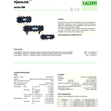
Hydronic separator-manifold HydroLink™
CALEFFI
series 559
cert. n° 0003
ISO 9001
01084/05 NA
Function The Hydrolink, a new device combining a hydronic separator and distribution manifold, is used in heating and air-conditioning systems to allow different heat adjustments of the various rooms when there is only one boiler or chiller. The various configurations are compact, and can be easily fitted in any kind of hydronic circuit, with the advantages of ease of installation and a saving of useful living space. Patent application No. MI2001A001270
Product range Code 559022A External 2+2 separator-manifold. Complete with support brackets and pre-formed insulation Code 559031A External 3+1 separator-manifold. Complete with support brackets and pre-formed insulation Cod e 559021A Bui l t-i n 2+ 1 se p a ra tor-ma ni fol d . Comp l e te wi th p re -for me d i nsul a ti on
Size 1 1/4”; branches 1” Size 1 1/4”; branc hes 1” Si z e 1”; b ra nc he s 1”
Technical characteristics Body
Insulation
Ma te ri a l : - Bod y :
Pa i nte d ste e l
Medium: Water and non-hazardous glycol solutions Ma x p e rc e nta g e of g l y c ol e : 50% Ma x. worki ng p re ssure : Te mp e ra ture ra ng e : Connections:
90 p si ( 6 b a r) 32 to 230°F ( 0 ÷ 110°C)
- main:
3+1 and 2+2: 2+1: - branches: 3+1 and 2+2: 2+1 (bottom): 2+1 (side): - air vent valve: 3+1, 2+2 and 2+1: - drain cock: 3+1, 2+2 and 2+1:
Center distances: - main: - branches:
3+1 and 2+2: 2+1: 3+1 and 2+2: 2+1:
1 1/4” F NPT 1” F NPT 1” M NPT 1” M NPT 1” F NPT 1/2” F straight 1/2” F straight 3 1/8” (80 mm) 2 3/8” (60 mm) 3 1/2” (90 mm) 3 1/2” (90 mm)
Ma te ri a l : Thi c kne ss: Density:
Cl ose d -c e l l e xp a nd e d PEX 3/4” ( 20 mm) - inner part: 2 lb/ft 3 (30 kg/m 3) - outer part: 3 lb/ft 3 (50 kg/m 3) Thermal conductivity: - at 32°F (0°C): 0.26 BTU/in (.038 W/mK) - at 100°F (40°C): 0.31 BTU/in (.045 W/mK) Vapor resistance coefficient (DIN 52615): > 1.300 Te mp e ra ture ra ng e : 32 to 212°F ( 0÷ 100°C) Fire resistance (DIN 4102): Class 1 (Class B2) Flow Characteristics Maximum recommended flow rates at connections: Branches 2+1 2+2 3+1
Primary 9 gpm (2.0 m 3/h) 11 gpm (2.5 m 3/h) 11 gpm (2.5 m 3/h)
Secondary (total) 22 gpm (5 m 3/h) 26 gpm (6 m 3/h) 26 gpm (6 m 3/h)
Dimensions
Operating principle When a single system contains a primary generating circuit, with its own pump, and a secondary user circuit, with one or more distribution pumps, operating conditions may arise in the system where the pumps interact, creating abnormal variations in flow rates and pressures in the circuits. In the HydroLink there is a low pressure loss zone, which enables the primary and secondary circuits connected to it to be hydraulically independent of each other; the flow in one circuit does not create a flow in the other if the pressure loss in the common section is negligible. In this case, the flow rates passing through the respective circuits depend exclusively on the flow characteristics of the pumps, preventing reciprocal influence due to connection in series. Downstream of the hydronic separation zone are the flow and return manifolds to which the various secondary distribution circuits can be connected.
A
C
I H
HydroLink™ Series 559 Pmax 90 psi - Tmax 230°F
A
38487
Patent Application No. MI2001A 001270
C D
Code
A
559022A 1 1/4”
B 1”
L
B E
C
F
G
D
E
F
G
H
I
L
1/2” 6 5/16” 3 9/16” 5 1/2” 20 7/8” 3 1/8” 9 7/8” 3 1/8”
C
Volume (gal)
29
1.8
G
Three possible hydronic balance situations are shown below as examples.
A
F
Weight (lb)
I H
HydroLink™ Series 559 Pmax 90 psi - Tmax 230°F 38503
A
Patent Application No. MI2001A 001270
secondary circuit C
B
D
Code
A
559031A 1 1/4”
B 1”
C
L D
E /F
M
E
G
H
I
L
M
1/2” 15 3/8” 3 9/16” 5 1/2” 3 1/8” 9 7/8” 29 15/16” 3 1/8”
Weight (lb)
Volume (gal)
39
2.6
C
A
H G
A
primary circuit HydroLink™ Series 559
A
Patent Application No. MI2001A 001270
A
38485
Pmax 90 psi - Tmax 230°F
B
C D
L E
Code
A
B
C
559021A
1”
1”
1/2”
GS1
F
D
I
E
F
H
I
L
6 1/8” 3 9/16” 20 1/2” 7 11/16” 3 9/16” 2 3/8”
GS2
GS3
Gp
Weight (lb)
Volume (gal)
16
1
GS1
GS2
GS3
Gp
GS4 Gprimary = Gsecondary (GS1+GS2+GS3+GS4)
GS1
GS2
GS3
Gp
GS4 Gprimary > Gsecondary (GS1+GS2+GS3+GS4)
GS4 Gprimary < Gsecondary (GS1+GS2+GS3+GS4)
Installation HydroLink units should be installed in accordance with the diagrams shown in this leaflet, ensuring the correct connection of the flow and return pipework and the main and branch connections. HydroLinks units can even be installed upside down, as long as the connection logic shown is adhered to. The 1/2” F connections must only be used for connecting an air vent valve and drain cock, and not for connecting branch circuits.
Insulation
CALEFFI
CALEFFI
100
2,25 2,0
1,75
80
1,0
2,0
1,75
80 1,5
16
-15
20
0,5
20
1,0
23
1,75 2,0
24
9
2,25
0,75 0,5
3
WATCH
10
1,25
5
0
-5
-10
-15
-20
0,25
1,5 1,75 2,0 2,25
1
2
10
10
9
3
6
8
4
7
5
6
3 4 5
20
40
0,25
15
11
1
21
1,5
11
2
16
12
0,25
60
0,75
17
20
12
6
18
12
-20
22
-10
6
22
-5
13
13
23
0
7
5
8
1,0 0,75 0,5
3
WATCH
10
1,25
14
14
24
1,0
19
40
20 15
15
15
21
0,5 0,25
20
9
1,25
60
0,75
17
9
18
12
The Hydrolink is supplied with heat-preformed shell insulation. This system ensures not only perfect heat insulation but also the tightness required to prevent atmospheric water vapour from entering the unit. For this reason, this type of insulation may also be used in cooling water circuits, as it prevents condensation from forming on the surface of the valve body.
100
2,25
1,5 1,25
19
20
20
Support brackets The HydroLink external versions 2+2 and 3+1 are supplied complete with suitable wall-mounting brackets, which make it possible to adjust the front-to-back positioning.
Application diagrams RT
35 40 45 50 55 60
40 20
60 80
0
CALEFFI
CALEFFI
°C
CALEFFI
10 8 6 4 2 0
40 20
10 8 6 4 2 0
10 8 6 4 2 0
60
10 8 6 4 2 0
10 8 6 4 2 0
CALEFFI
10 8 6 4 2 0
CALEFFI
80
0
°C
RT
35 40 45
20
50 55 60
40 20
60 80
0
CALEFFI
CALEFFI
°C
CALEFFI
CALEFFI
30 25
CALEFFI
20
CALEFFI
30 25
CALEFFI
System with wall-mounted boiler and built-in HydroLink 2+1
10 8 6 4 2 0
40 20
60 80
0
°C
10 8 6 4 2 0
10 8 6 4 2 0
10 8 6 4 2 0
CALEFFI
10 8 6 4 2 0
10 8 6 4 2 0
CALEFFI
M S
-
+ 20
System with floor standing boiler and HydroLink 3+1
18
CALEFFI
22
16
24
CALEFFI
CALEFFI
CALEFFI
CALEFFI
10 8 6 4 2 0
10 8 6 4 2 0
10 8 6 4 2 0
10 8 6 4 2 0
10 8 6 4 2 0
10 8 6 4 2 0
CALEFFI
CALEFFI
M S
-
+ 20
18
CALEFFI
10 8 6 4 2 0
10 8 6 4 2 0
10 8 6 4 2 0
CALEFFI
2,25
100 2,0 1,75 1,5
80
CALEFFI
2,25
1,0
0,5
5
0
-5
-10
-15
-20
CALEFFI
100
1,5
1,0
80
60
0,75 40
0,5
0,25 10
1,25
10 8 6 4 2 0
1,25 60
0,75
15
1,0
10 8 6 4 2 0
2,0 1,75
1,25
20
0,75 0,5 0,25
22 24
CALEFFI
CALEFFI
10 8 6 4 2 0
CALEFFI
16
CALEFFI
CALEFFI
40
0,25 20
20
1,5
15
1,0 1,75
0,75
2,0
0,5
2,25
0,25
10
1,25
5
0
-5
-10
-15
-20
20
1,5 1,75 2,0 2,25
9
8 20
20
SPECIFICATION SUMMARIES Code 559022A External hydraulic separator-manifold, branches 2+2, for heating and air-conditioning systems. Painted steel body. Connections to generator 1 1/4” F, centre distance 3 1/8” (80 mm). Branch connections 1” M, centre distance 3 1/2” (90 mm) . 1/2” F connections for air vent valve and drain cock. Max. working pressure 90 psi (6 bar) . Temperature range 32 to 230°F (0÷110°C) . Complete with support brackets. Code 559031A External hydraulic separator-manifold, branches 3+1, for heating and air-conditioning systems. Painted steel body. Connections to generator 1 1/4” F, centre distance 3 1/8” (80 mm) . Branch connections 1” M, centre distance 3 1/2” (90 mm) . 1/2” F connections for air vent valve and drain cock. Max. working pressure 90 psi (6 bar) . Temperature range 32 to 230°F (0÷110°C) . Complete with support brackets. Code 559021A Built-in hydraulic separator-manifold, branches 2+1, for heating and air-conditioning systems. Painted steel body. Connections to generator 1” F, centre distance 2 3/8” (60 mm) . Side branch connections 1” M, centre distance 3 1/2” (90 mm) . Head branch connections 1” F, centre distance 2 3/8” (60 mm) . 1/2” F connections for air vent valve and drain cock. Max. working pressure 90 psi (6 bar) . Temperature range 32 to 230°F (0÷110°C) .
We reserve the right to change our products and their relevant technical data, contained in this publication, at any time and without prior notice.
CALEFFI Caleffi North America, Inc.
9850 South 54th Street / Milwaukee, WI 53132 Tel: 414.421.1000 / Fax: 414.421.2878 / www.caleffi.us © Copyright 2005 Caleffi North America, Inc.
CALEFFI
series 559
cert. n° 0003
ISO 9001
01084/05 NA
Function The Hydrolink, a new device combining a hydronic separator and distribution manifold, is used in heating and air-conditioning systems to allow different heat adjustments of the various rooms when there is only one boiler or chiller. The various configurations are compact, and can be easily fitted in any kind of hydronic circuit, with the advantages of ease of installation and a saving of useful living space. Patent application No. MI2001A001270
Product range Code 559022A External 2+2 separator-manifold. Complete with support brackets and pre-formed insulation Code 559031A External 3+1 separator-manifold. Complete with support brackets and pre-formed insulation Cod e 559021A Bui l t-i n 2+ 1 se p a ra tor-ma ni fol d . Comp l e te wi th p re -for me d i nsul a ti on
Size 1 1/4”; branches 1” Size 1 1/4”; branc hes 1” Si z e 1”; b ra nc he s 1”
Technical characteristics Body
Insulation
Ma te ri a l : - Bod y :
Pa i nte d ste e l
Medium: Water and non-hazardous glycol solutions Ma x p e rc e nta g e of g l y c ol e : 50% Ma x. worki ng p re ssure : Te mp e ra ture ra ng e : Connections:
90 p si ( 6 b a r) 32 to 230°F ( 0 ÷ 110°C)
- main:
3+1 and 2+2: 2+1: - branches: 3+1 and 2+2: 2+1 (bottom): 2+1 (side): - air vent valve: 3+1, 2+2 and 2+1: - drain cock: 3+1, 2+2 and 2+1:
Center distances: - main: - branches:
3+1 and 2+2: 2+1: 3+1 and 2+2: 2+1:
1 1/4” F NPT 1” F NPT 1” M NPT 1” M NPT 1” F NPT 1/2” F straight 1/2” F straight 3 1/8” (80 mm) 2 3/8” (60 mm) 3 1/2” (90 mm) 3 1/2” (90 mm)
Ma te ri a l : Thi c kne ss: Density:
Cl ose d -c e l l e xp a nd e d PEX 3/4” ( 20 mm) - inner part: 2 lb/ft 3 (30 kg/m 3) - outer part: 3 lb/ft 3 (50 kg/m 3) Thermal conductivity: - at 32°F (0°C): 0.26 BTU/in (.038 W/mK) - at 100°F (40°C): 0.31 BTU/in (.045 W/mK) Vapor resistance coefficient (DIN 52615): > 1.300 Te mp e ra ture ra ng e : 32 to 212°F ( 0÷ 100°C) Fire resistance (DIN 4102): Class 1 (Class B2) Flow Characteristics Maximum recommended flow rates at connections: Branches 2+1 2+2 3+1
Primary 9 gpm (2.0 m 3/h) 11 gpm (2.5 m 3/h) 11 gpm (2.5 m 3/h)
Secondary (total) 22 gpm (5 m 3/h) 26 gpm (6 m 3/h) 26 gpm (6 m 3/h)
Dimensions
Operating principle When a single system contains a primary generating circuit, with its own pump, and a secondary user circuit, with one or more distribution pumps, operating conditions may arise in the system where the pumps interact, creating abnormal variations in flow rates and pressures in the circuits. In the HydroLink there is a low pressure loss zone, which enables the primary and secondary circuits connected to it to be hydraulically independent of each other; the flow in one circuit does not create a flow in the other if the pressure loss in the common section is negligible. In this case, the flow rates passing through the respective circuits depend exclusively on the flow characteristics of the pumps, preventing reciprocal influence due to connection in series. Downstream of the hydronic separation zone are the flow and return manifolds to which the various secondary distribution circuits can be connected.
A
C
I H
HydroLink™ Series 559 Pmax 90 psi - Tmax 230°F
A
38487
Patent Application No. MI2001A 001270
C D
Code
A
559022A 1 1/4”
B 1”
L
B E
C
F
G
D
E
F
G
H
I
L
1/2” 6 5/16” 3 9/16” 5 1/2” 20 7/8” 3 1/8” 9 7/8” 3 1/8”
C
Volume (gal)
29
1.8
G
Three possible hydronic balance situations are shown below as examples.
A
F
Weight (lb)
I H
HydroLink™ Series 559 Pmax 90 psi - Tmax 230°F 38503
A
Patent Application No. MI2001A 001270
secondary circuit C
B
D
Code
A
559031A 1 1/4”
B 1”
C
L D
E /F
M
E
G
H
I
L
M
1/2” 15 3/8” 3 9/16” 5 1/2” 3 1/8” 9 7/8” 29 15/16” 3 1/8”
Weight (lb)
Volume (gal)
39
2.6
C
A
H G
A
primary circuit HydroLink™ Series 559
A
Patent Application No. MI2001A 001270
A
38485
Pmax 90 psi - Tmax 230°F
B
C D
L E
Code
A
B
C
559021A
1”
1”
1/2”
GS1
F
D
I
E
F
H
I
L
6 1/8” 3 9/16” 20 1/2” 7 11/16” 3 9/16” 2 3/8”
GS2
GS3
Gp
Weight (lb)
Volume (gal)
16
1
GS1
GS2
GS3
Gp
GS4 Gprimary = Gsecondary (GS1+GS2+GS3+GS4)
GS1
GS2
GS3
Gp
GS4 Gprimary > Gsecondary (GS1+GS2+GS3+GS4)
GS4 Gprimary < Gsecondary (GS1+GS2+GS3+GS4)
Installation HydroLink units should be installed in accordance with the diagrams shown in this leaflet, ensuring the correct connection of the flow and return pipework and the main and branch connections. HydroLinks units can even be installed upside down, as long as the connection logic shown is adhered to. The 1/2” F connections must only be used for connecting an air vent valve and drain cock, and not for connecting branch circuits.
Insulation
CALEFFI
CALEFFI
100
2,25 2,0
1,75
80
1,0
2,0
1,75
80 1,5
16
-15
20
0,5
20
1,0
23
1,75 2,0
24
9
2,25
0,75 0,5
3
WATCH
10
1,25
5
0
-5
-10
-15
-20
0,25
1,5 1,75 2,0 2,25
1
2
10
10
9
3
6
8
4
7
5
6
3 4 5
20
40
0,25
15
11
1
21
1,5
11
2
16
12
0,25
60
0,75
17
20
12
6
18
12
-20
22
-10
6
22
-5
13
13
23
0
7
5
8
1,0 0,75 0,5
3
WATCH
10
1,25
14
14
24
1,0
19
40
20 15
15
15
21
0,5 0,25
20
9
1,25
60
0,75
17
9
18
12
The Hydrolink is supplied with heat-preformed shell insulation. This system ensures not only perfect heat insulation but also the tightness required to prevent atmospheric water vapour from entering the unit. For this reason, this type of insulation may also be used in cooling water circuits, as it prevents condensation from forming on the surface of the valve body.
100
2,25
1,5 1,25
19
20
20
Support brackets The HydroLink external versions 2+2 and 3+1 are supplied complete with suitable wall-mounting brackets, which make it possible to adjust the front-to-back positioning.
Application diagrams RT
35 40 45 50 55 60
40 20
60 80
0
CALEFFI
CALEFFI
°C
CALEFFI
10 8 6 4 2 0
40 20
10 8 6 4 2 0
10 8 6 4 2 0
60
10 8 6 4 2 0
10 8 6 4 2 0
CALEFFI
10 8 6 4 2 0
CALEFFI
80
0
°C
RT
35 40 45
20
50 55 60
40 20
60 80
0
CALEFFI
CALEFFI
°C
CALEFFI
CALEFFI
30 25
CALEFFI
20
CALEFFI
30 25
CALEFFI
System with wall-mounted boiler and built-in HydroLink 2+1
10 8 6 4 2 0
40 20
60 80
0
°C
10 8 6 4 2 0
10 8 6 4 2 0
10 8 6 4 2 0
CALEFFI
10 8 6 4 2 0
10 8 6 4 2 0
CALEFFI
M S
-
+ 20
System with floor standing boiler and HydroLink 3+1
18
CALEFFI
22
16
24
CALEFFI
CALEFFI
CALEFFI
CALEFFI
10 8 6 4 2 0
10 8 6 4 2 0
10 8 6 4 2 0
10 8 6 4 2 0
10 8 6 4 2 0
10 8 6 4 2 0
CALEFFI
CALEFFI
M S
-
+ 20
18
CALEFFI
10 8 6 4 2 0
10 8 6 4 2 0
10 8 6 4 2 0
CALEFFI
2,25
100 2,0 1,75 1,5
80
CALEFFI
2,25
1,0
0,5
5
0
-5
-10
-15
-20
CALEFFI
100
1,5
1,0
80
60
0,75 40
0,5
0,25 10
1,25
10 8 6 4 2 0
1,25 60
0,75
15
1,0
10 8 6 4 2 0
2,0 1,75
1,25
20
0,75 0,5 0,25
22 24
CALEFFI
CALEFFI
10 8 6 4 2 0
CALEFFI
16
CALEFFI
CALEFFI
40
0,25 20
20
1,5
15
1,0 1,75
0,75
2,0
0,5
2,25
0,25
10
1,25
5
0
-5
-10
-15
-20
20
1,5 1,75 2,0 2,25
9
8 20
20
SPECIFICATION SUMMARIES Code 559022A External hydraulic separator-manifold, branches 2+2, for heating and air-conditioning systems. Painted steel body. Connections to generator 1 1/4” F, centre distance 3 1/8” (80 mm). Branch connections 1” M, centre distance 3 1/2” (90 mm) . 1/2” F connections for air vent valve and drain cock. Max. working pressure 90 psi (6 bar) . Temperature range 32 to 230°F (0÷110°C) . Complete with support brackets. Code 559031A External hydraulic separator-manifold, branches 3+1, for heating and air-conditioning systems. Painted steel body. Connections to generator 1 1/4” F, centre distance 3 1/8” (80 mm) . Branch connections 1” M, centre distance 3 1/2” (90 mm) . 1/2” F connections for air vent valve and drain cock. Max. working pressure 90 psi (6 bar) . Temperature range 32 to 230°F (0÷110°C) . Complete with support brackets. Code 559021A Built-in hydraulic separator-manifold, branches 2+1, for heating and air-conditioning systems. Painted steel body. Connections to generator 1” F, centre distance 2 3/8” (60 mm) . Side branch connections 1” M, centre distance 3 1/2” (90 mm) . Head branch connections 1” F, centre distance 2 3/8” (60 mm) . 1/2” F connections for air vent valve and drain cock. Max. working pressure 90 psi (6 bar) . Temperature range 32 to 230°F (0÷110°C) .
We reserve the right to change our products and their relevant technical data, contained in this publication, at any time and without prior notice.
CALEFFI Caleffi North America, Inc.
9850 South 54th Street / Milwaukee, WI 53132 Tel: 414.421.1000 / Fax: 414.421.2878 / www.caleffi.us © Copyright 2005 Caleffi North America, Inc.
Related Documents
Caleffi Hydrolink Brochure
June 2020 2
Caleffi Isolar Control Brochure
June 2020 4
Caleffi Discal Air Separators Brochure
June 2020 11
Caleffi Solar Pump Station Brochure
June 2020 4
