Cable Heaters Versatile
This document was uploaded by user and they confirmed that they have the permission to share it. If you are author or own the copyright of this book, please report to us by using this DMCA report form. Report DMCA
Overview
Download & View Cable Heaters Versatile as PDF for free.
More details
- Words: 2,767
- Pages: 7
Cable Heaters
11/28/00
1:54 PM
Page 57
W
A
T
L
O
W
Cable Heaters Versatile, Standard Cable Heaters
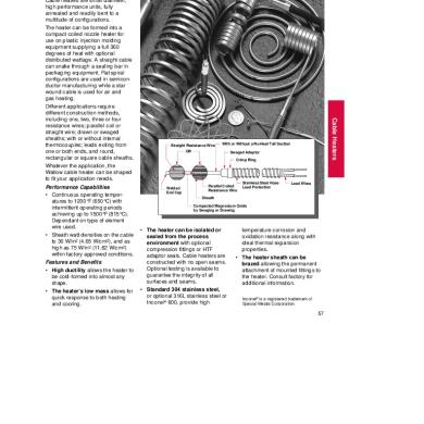
Performance Capabilities • Continuous operating temperatures to 1200°F (650°C) with intermittent operating periods achieving up to 1500°F (815°C). Dependant on type of element wire used. • Sheath watt densities on the cable to 30 W/in2 (4.65 W/cm2), and as high as 75 W/in2 (11.62 W/cm2) within factory approved conditions. Features and Benefits • High ductility allows the heater to be cold-formed into almost any shape. • The heater’s low mass allows for quick response to both heating and cooling.
Straight Resistance Wire
Cable Heaters
The versatile Watlow cable heater can be formed to a variety of shapes as dictated by its many applications. Cable heaters are small diameter, high performance units, fully annealed and readily bent to a multitude of configurations. The heater can be formed into a compact coiled nozzle heater for use on plastic injection molding equipment supplying a full 360 degrees of heat with optional distributed wattage. A straight cable can snake through a sealing bar in packaging equipment. Flat spiral configurations are used in semiconductor manufacturing while a star wound cable is used for air and gas heating. Different applications require different construction methods, including one, two, three or four resistance wires; parallel coil or straight wire; drawn or swaged sheaths; with or without internal thermocouples; leads exiting from one or both ends, and round, rectangular or square cable sheaths. Whatever the application, the Watlow cable heater can be shaped to fit your application needs.
With or Without a No-Heat Tail Section
OR
Swaged Adaptor Crimp Ring
Welded End Cap
Parallel Coiled Resistance Wire
Stainless Steel Hose Lead Protection
Lead Wires
Sheath Compacted Magnesium Oxide by Swaging or Drawing
• The heater can be isolated or sealed from the process environment with optional compression fittings or HTF adaptor seals. Cable heaters are constructed with no open seams. Optional testing is available to guarantee the integrity of all surfaces and seams. • Standard 304 stainless steel, or optional 316L stainless steel or Inconel® 600, provide high
temperature corrosion and oxidation resistance along with ideal thermal expansion properties. • The heater sheath can be brazed allowing the permanent attachment of mounted fittings to the heater. Consult factory for additional information. Inconel® is a registered trademark of Special Metals Corporation.
57
Cable Heaters
11/28/00
1:54 PM
Page 58
Cable Heaters Versatile, Standard Cable Heaters Features Continued
• Ranging from 0.040 inch (1 mm) to 0.188 inch (5 mm) diameter, the cable heater packs a lot of heat into a tiny space. Lengths range from 3⁄4 inch (19 mm) to over 70 feet (2134 cm). • Internal construction options allow internal thermocouples and
no-heat sections. (Not available in all sizes.) • Cable heaters can operate in unusual environments, including cryogenic and sub-freezing temperatures, high vacuum, and gaseous and liquid immersion conditions.
Applications • Plastic injection molding nozzles • Semiconductor manufacturing and wafer processing • Hot metal forming dies and punches • Sealing and cutting bars • Medical, analytical and scientific instruments
• Restaurant and food processing equipment • Cast-in heaters • Laminating and printing presses • Air heating • Textile manufacturing • Heating in a vacuum environment
Electrical Data and Coiling Limits Sheath Diameter
Maximum Voltage
inches
(mm)
Surface Area Per Linear Foot in (cm)
Minimum Bend Radius in (mm)
Minimum Coiled Inside Diameter in (mm)
0.040 ± 0.002 0.062 ± 0.002 0.058 ± 0.002 0.094 + 0.002 - 0.003 0.102 square ± 0.003
(1.016 ± 0.051) (1.575 ± 0.051) (1.473 ± 0.051) (2.388 + 0.051 - 0.076) (2.591 ± 0.076)
48 120 240 240 240
1.51 2.34 2.18 3.54 4.90
(9.743) (15.098) (14.065) (22.840) (31.615)
⁄16 ⁄8 1 ⁄8 3 ⁄16 1 ⁄4
(1.588) (3.175) (3.175) (4.763) (6.350)
1
0.103 ± 0.003 x 0.153 ± 0.005 rectangular
(2.667 ± 0.076) x (3.886 ± 0.127)
240
6.19
(39.938)
1
⁄4
(6.350)
0.125 ± 0.003 0.157 ± 0.004 0.188 + 0.003 - 0.006 0.128 square ± 0.003
(3.175 ± 0.076) (3.998 ± 0.102) (4.775 + 0.076 - 0.152) (3.353 ± 0.076)
240 240 240 240
4.71 5.92 7.09 6.31
(30.389) (38.196) (45.745) (40.712)
⁄4 5 ⁄16 3 ⁄8 1 ⁄4
(6.350) (7.938) (9.525) (6.350)
1
1
1
1
⁄8 ⁄4 1 ⁄4 3 ⁄8 1 ⁄2
(3.175) (6.350) (6.350) (9.525) (12.700)
1
⁄2
(12.700)
⁄2 5 ⁄8 3 ⁄4 1 ⁄2
(12.700) (15.875) (19.050) (12.700)
1
In most cases 30 W/in2 (4.65 W/cm2) is the safe allowable limit for cable watt density. Please consult factory before ordering >30 WSI cables. Standard Resistance/Wattage Tolerance ±10 percent. Cable heaters can run on both ac and dc, 50 or 60Hz. Consult factory for amperage limitations.
Coiling Tolerances Standard Coiled Width Tolerances Cable Diameters All Diameters
Coiled Width inches (mm)
Standard Coiled I.D. Tolerances
Tolerances inches (mm)
Below 6 (152.4) + 0 - 1⁄8 (+0.000 - 3.175) 6 to 10 (152.4 to 254.0) + 1⁄8 - 3⁄8 (+3.175 - 9.525) Over 10 (Over 254.0) + 1⁄4 - 1⁄4 (+6.350 - 6.350)
Coil I.D. Range inches (mm) Below 0.625 0.625 to 0.999 1.000 to 1.999 2.000 to 2.999 3.000 to 3.999 4.000 to 4.999 5.000 and Over
Tolerances inches (mm)
(Below 15.875) (15.875 to 25.375) (25.400 to 50.775) (50.800 to 76.175) (76.200 to 101.575) (101.600 to 126.975) (127.000 and Over)
+0.000 - 0.015 +0.000 - 0.030 +0.000 - 0.062 +0.000 - 0.125 +0.000 - 0.250 +0.000 - 0.375 +0.000 - 0.500
(+0 - 0.381) (+0 - 0.762) (+0 - 1.575) (+0 - 3.175) (+0 - 6.350) (+0 - 9.525) (+0 - 12.700)
When the O.D. of the coil is required to be the critical dimension, this fact must be specified at the time of ordering so that proper coiling procedures can be determined. I.D. and O.D. dimensions cannot be held on the same unit. Please consult with the factory before ordering coiled cable heaters requiring other than standard tolerances.
Cable Straight Length Tolerances
Length Tolerance
58
≤24" ±3⁄8"
>24"≤60" ±1⁄2"
>60"≤100" ±1"
>100" ±1%
Cable Heaters
11/28/00
1:54 PM
Page 59
W
A
T
L
O
W
Cable Heaters Versatile, Standard Cable Heaters
Standard Coil The standard coil can be tight wound, open pitch or anything in between.
Formation Options
Closed Coil without Distributed Wattage
Closed Coil with Distributed Wattage
Lead Orientation Options for Coiled Cable Heaters Width Width
Width 90°
I.D.
I.D.
I.D. 1/8" ± 1/8" (3 mm ±3 mm)
Tail Section
90° 1" ± 1/8" (25 mm ± 3 mm)
Tail Section
1 4"
/ (6 mm) R
3/8" ± 1/8" (10 mm ± 3 mm)
Tail Section Nom. 3/8" (10 mm) O.D.
I.D. 45°
Tail Section
1" ± 1/8" (25 mm ± 3 mm)
Cable Heaters
Width
Option 2B
OptionOption 2F 2F
Option 2C
Option 2A
Flat Spiral Flat spiral formations are used to heat flat circular surfaces. This formation is often used in semiconductor and medical applications. Flat Spiral with 2A Type Lead Orientation
Flat Spiral with 2C Flat Spiral with 2F Type Lead Orientation Type Lead Orientation
Sinuated Sinuated cable heaters provide an alternative to the flat spiral coil heater, allowing greater coverage of
flat rectangular surfaces. The sinuated formation can also be curved to heat cylindrical shapes. This formation is often used in radiant heating applications.
Star Wound Star wound formations are usually inserted into pipes or ducts and are used to heat moving air or liquids. The offset coils increase/induce
turbulent flow. This allows the flowing material to have better contact with the heater surface, resulting in a more efficient heat transfer.
59
Cable Heaters
11/28/00
1:54 PM
Page 60
Cable Heaters Versatile, Standard Cable Heaters
Sheath with Coiled Internal Resistance Wire 72" (1829 mm) Maximum Length
Standard Internal Construction
Heated Section
No-Heat Section Sheath
Sheath Swaged to Size High Density Magnesium Oxide
Mate with Adaptor No Junction in the Resistance Wire End Disk Welded Prior to Swaging
No-Heat Pins
Coiled Resistance Wire
Parallel Coil Construction
Resistance wire, wound into a small coil, is loaded into insulating cores, then into metal tubing and swaged to final size. This method of construction is called parallel coil. The parallel coil method allows for a no-heat section in the sheath. The length of either the heated section or no-heat section is variable as long as the combined length does not exceed 72 inches (1830 mm). Other
features of this construction method • A variety of diameters and shapes: include: 0.058 inch (1.473 mm) round • Variable ohms/foot within a 0.094 inch (2.387 mm) round minimum and maximum range 0.125 inch (3.175 mm) round (min. • Variable location of the dia. with internal thermocouple) thermocouple junction 0.102 (2.591 mm) inch square • Grounded or ungrounded 0.128 inch (3.251 mm) square thermocouple junction 0.103 inch X 0.153 inch • No-heat sections (2.616 mm X 3.886 mm) rectangular • 304 stainless steel, 316L stainless steel or Inconel® 600 sheath material Sheath with Straight (Uncoiled) Resistance Wire Heated Length Compacted Magnesium Oxide from Drawing Process Sheath
Mate with Adaptor Sheath Drawn to Size Resistance Wires Junctioned after Sheath is Drawn to Size Straight Resistance Wire from End to End
End Disk Welded after Resistance Wires are Junctioned
Drawn Cable Construction
Uncoiled resistance wires are positioned inside a large diameter metal tube. The tube assembly is repeatedly pulled through draw dies until the desired diameter is achieved. Though limited to fixed incremental ohms/foot and without no-heat sections, this drawn cable construction method does allow: • Essentially no limit on cable length
60
• Thermocouple junction only at the disk end of the sheath • Grounded or ungrounded thermocouple junction • Sheath heated from end to end • 304 stainless steel, 316L stainless steel or Inconel® 600 sheath material • A variety of diameters and shapes: 0.040 inch (1.016 mm) round
0.062 inch (1.575 mm) round 0.094 inch (2.388 mm) round 0.125 inch (3.175 mm) round (min. dia. with internal thermocouple) 0.157 inch (3.988 mm) round 0.188 inch (4.775 mm) round 0.128 inch (3.251 mm) square 0.103 inch X 0.153 inch (2.616 mm X 3.886 mm) rectangular
Cable Heaters
11/28/00
1:54 PM
Page 61
W
A
T
L
O
W
Cable Heaters Versatile, Standard Cable Heaters Options Internal Construction
Disk End of Sheath Junction Cavity is Backfilled with Magnesium Oxide after Resistance Wires are Junctioned
No Wire Junction in the Resistance Wire—Made from One Continuous Length of Resistance Wire End Disk Welded Prior to Swaging
End Disk Welded after Resistance Wires Are Junctioned
Resistance Wires Junctioned after Sheath is Drawn to Size Sheath
Sheath Coiled Resistance Wire
Straight Resistance Wire
High Density Magnesium Oxide from the Swaging Process
Compacted Magnesium Oxide from Drawing Process
With drawn cable construction, the internal wires, whether resistance or thermocouple, must be junctioned before the heater sheath can be finished. Magnesium oxide is removed from the tip of the sheath, exposing the wires which are then junctioned by welding. Magnesium oxide powder is backfilled into the cavity surrounding the junctioned wires and lightly compacted. The end cap is inserted and welded into place.
Thermocouples Internal thermocouples are available in ASTM Type J or K calibration with both the parallel coil or drawn cable construction methods.➀ Parallel Coil: 0.125 inch round 0.128 inch X 0.128 inch square 0.103 inch X 0.153 inch rectangular
Drawn Cable: 0.125 inch round 0.157 inch round 0.188 inch round 0.128 inch X 0.128 inch square 0.103 inch X 0.153 inch rectangular External thermocouples with Type J or K calibration can be spot welded or brazed to the heater sheath. The sheath size must be a minimum of 0.094 inch in diameter. Hose clamps can more easily be used to secure the thermocouple.
➀ Other thermocouple types available. Consult factory.
61
Cable Heaters
The end of the heater sheath opposite from the lead end is called the disk end. With parallel coil construction methods, the internal resistance wires form a 180 degree bend inside the sheath and, so, do not require a junction. After the end cap has been welded in place, the entire area at the end of the sheath is swaged to provide maximum density of the magnesium oxide.
Cable Heaters
11/28/00
1:54 PM
Page 62
Cable Heaters Versatile, Standard Cable Heaters Options Internal Construction Continued
Adaptors Adaptors are the transition sections where the lead wires are attached to the heater sheaths. The lead wires are connected with the internal wires from the sheath. Sheath Collar Welded/Brazed to Adaptor Case Collar Welded to Sheath
Lead Wire Positive Connection Lap Joint Welded/Brazed
The positive connection lap joint brazes or welds the wire lap joint before the adaptor is swaged. Positive connection is used in all standard applications and provides added protection in high temperature environments and other severe and demanding applications. An extended length adaptor collar, or high temperature collar, is used as a heat sink allowing the heater to be operated in high temperature and other demanding applications. The positive connection and collar are used in conjunction with both power leads and thermocouple leads.
High Density Magnesium Oxide High Temperature Adaptor Collar Compacted Magnesium Oxide
External Construction
62
Lead Wire: 100 percent nickel, copper, nickel plated copper or silver plated copper.
Insulation: Teflon®, fiberglass, or a high temperature variety such as MGT or MGE. Consult factory for other wire options.
Lead Protection: Stainless steel hose, stainless steel braid or fiberglass braid.
Consult factory for details.
Special Fittings • VCR® and VCO® vacuum fittings or similar • Ultra-Torr® compression fittings or similar
• Threaded screw headers • Flanges • Heat sinks Consult factory for details.
Teflon® is a registered trademark of E.I. du Pont de Nemours & Company.
VCR®, VCO® and Ultra-Torr® are registered trademarks of the Swagelok Company.
Cable Heaters
11/28/00
1:54 PM
Page 63
W
A
T
L
O
Cable Heaters
W
F.O.B.: St. Louis, Missouri
Versatile, Standard Cable Heaters
How to Order To order your stock cable heater, specify: • Watlow code number and/or voltage and wattage specifications • Forming options (required information): Straight - standard option unless otherwise specified Nozzle - coil I.D., coil width, lead orientation Distributed nozzle - coil I.D., coil width, lead orientation, number of zones Sinuated - height, width, bend radius, lead orientation
Starwound - coil O.D., coil width, lead orientation Flat spiral - spiral I.D., spiral width, lead orientation • Lead wire options (required information): Standard - 14 inch crimped-on fbg unless otherwise noted Fiberglass - various lengths available Teflon® - various lengths available • Lead protection options (required information): Standard - 12 inch crimped-on stainless steel hose unless otherwise noted SS hose - various lengths available SS braid - various lengths available
Fiberglass braid - various lengths available • Internal thermocouple option: Type J thermocouple See stock product list for available units. • Special adders If the stock units do not meet application needs, consult factory for a quote on made-to-order units. Availability Stock: Straight units can be formed on request requiring one to two working days, contingent upon quantity and required options. Made-to-Order: Delivery dependent on complexity of order. Consult factory for price and delivery quotations.
Cable Heaters
Cable Heater Stock Units (Internal Thermocouple Not Available) Straight Cable Length in (mm)
Volts
Watts
Watt Density W/in2 W/cm2
No-Heat Length in (mm)
Lead Wire
Lead Protection
Code Number
14" (355.6 mm) Fiberglass unless otherwise specified
12" (304.8 mm) SS hose unless otherwise specified
62H24A6X 62H36A5X 62H56A4X 62H65A3X
36" (914.4 mm) swaged-in Teflon® leads only
Lead protection not available
94PC30A1X 94PC30A2X
14" (355.6 mm) Fiberglass unless otherwise specified
12" (304.8 mm) SS hose unless otherwise specified
125CH18A4X 125CH19A1X 125CH24A1X 125CH24A14X 125CH38A1X
0.062-inch Diameter Round (with ±10 percent wattage tolerance) 24 36 56 65
(609.6) (914.4) (1422.4) (1651.0)
120 120 120 120
240 400 330 500
51 57 30 39
(7.9) (8.8) (4.7) (6.0)
0.00 0.00 0.00 0.00
(0.00) (0.00) (0.00) (0.00)
0.094-inch Diameter Round (with ±5 percent wattage tolerance) 30 30
(762.0) (762.0)
230 230
125 250
17 34
(2.6) (5.3)
5.00 (127.00) 5.00 (127.00)
0.125 inch Diameter Round (with ±10 percent wattage tolerance) 18 19 24 24 38
(457.2) (482.6) (609.6) (609.6) (965.2)
240 120 120 240 240
250 165 275 275 325
35 21 29 29 21
(5.4) (3.3) (4.5) (4.5) (3.3)
1.50 1.50 1.50 1.50 1.50
(38.10) (38.10) (38.10) (38.10) (38.10)
38 47 47 47 47
(965.2) (1193.8) (1193.8) (1193.8) (1193.8)
120 240 120 120 240
175 260 235 375 345
12 14 12 20 19
(1.9) (2.2) (1.9) (3.1) (2.9)
1.50 1.50 1.50 1.50 1.50
(38.10) (38.10) (38.10) (38.10) (38.10)
125CH38A2X 125CH47A1X 125CH47A2X 125CH47A3X 125CH47A4X
65 65 95
(1651.0) (1651.0) (2413.0)
240 240 240
420 675 1000
16 27 28
(2.5) (4.2) (4.3)
1.50 (38.10) 1.50 (38.10) 0.00 (0.00)
125CH65A1X 125CH65A2X 125CH93A1X CONTINUED
63
11/28/00
1:54 PM
Page 57
W
A
T
L
O
W
Cable Heaters Versatile, Standard Cable Heaters
Performance Capabilities • Continuous operating temperatures to 1200°F (650°C) with intermittent operating periods achieving up to 1500°F (815°C). Dependant on type of element wire used. • Sheath watt densities on the cable to 30 W/in2 (4.65 W/cm2), and as high as 75 W/in2 (11.62 W/cm2) within factory approved conditions. Features and Benefits • High ductility allows the heater to be cold-formed into almost any shape. • The heater’s low mass allows for quick response to both heating and cooling.
Straight Resistance Wire
Cable Heaters
The versatile Watlow cable heater can be formed to a variety of shapes as dictated by its many applications. Cable heaters are small diameter, high performance units, fully annealed and readily bent to a multitude of configurations. The heater can be formed into a compact coiled nozzle heater for use on plastic injection molding equipment supplying a full 360 degrees of heat with optional distributed wattage. A straight cable can snake through a sealing bar in packaging equipment. Flat spiral configurations are used in semiconductor manufacturing while a star wound cable is used for air and gas heating. Different applications require different construction methods, including one, two, three or four resistance wires; parallel coil or straight wire; drawn or swaged sheaths; with or without internal thermocouples; leads exiting from one or both ends, and round, rectangular or square cable sheaths. Whatever the application, the Watlow cable heater can be shaped to fit your application needs.
With or Without a No-Heat Tail Section
OR
Swaged Adaptor Crimp Ring
Welded End Cap
Parallel Coiled Resistance Wire
Stainless Steel Hose Lead Protection
Lead Wires
Sheath Compacted Magnesium Oxide by Swaging or Drawing
• The heater can be isolated or sealed from the process environment with optional compression fittings or HTF adaptor seals. Cable heaters are constructed with no open seams. Optional testing is available to guarantee the integrity of all surfaces and seams. • Standard 304 stainless steel, or optional 316L stainless steel or Inconel® 600, provide high
temperature corrosion and oxidation resistance along with ideal thermal expansion properties. • The heater sheath can be brazed allowing the permanent attachment of mounted fittings to the heater. Consult factory for additional information. Inconel® is a registered trademark of Special Metals Corporation.
57
Cable Heaters
11/28/00
1:54 PM
Page 58
Cable Heaters Versatile, Standard Cable Heaters Features Continued
• Ranging from 0.040 inch (1 mm) to 0.188 inch (5 mm) diameter, the cable heater packs a lot of heat into a tiny space. Lengths range from 3⁄4 inch (19 mm) to over 70 feet (2134 cm). • Internal construction options allow internal thermocouples and
no-heat sections. (Not available in all sizes.) • Cable heaters can operate in unusual environments, including cryogenic and sub-freezing temperatures, high vacuum, and gaseous and liquid immersion conditions.
Applications • Plastic injection molding nozzles • Semiconductor manufacturing and wafer processing • Hot metal forming dies and punches • Sealing and cutting bars • Medical, analytical and scientific instruments
• Restaurant and food processing equipment • Cast-in heaters • Laminating and printing presses • Air heating • Textile manufacturing • Heating in a vacuum environment
Electrical Data and Coiling Limits Sheath Diameter
Maximum Voltage
inches
(mm)
Surface Area Per Linear Foot in (cm)
Minimum Bend Radius in (mm)
Minimum Coiled Inside Diameter in (mm)
0.040 ± 0.002 0.062 ± 0.002 0.058 ± 0.002 0.094 + 0.002 - 0.003 0.102 square ± 0.003
(1.016 ± 0.051) (1.575 ± 0.051) (1.473 ± 0.051) (2.388 + 0.051 - 0.076) (2.591 ± 0.076)
48 120 240 240 240
1.51 2.34 2.18 3.54 4.90
(9.743) (15.098) (14.065) (22.840) (31.615)
⁄16 ⁄8 1 ⁄8 3 ⁄16 1 ⁄4
(1.588) (3.175) (3.175) (4.763) (6.350)
1
0.103 ± 0.003 x 0.153 ± 0.005 rectangular
(2.667 ± 0.076) x (3.886 ± 0.127)
240
6.19
(39.938)
1
⁄4
(6.350)
0.125 ± 0.003 0.157 ± 0.004 0.188 + 0.003 - 0.006 0.128 square ± 0.003
(3.175 ± 0.076) (3.998 ± 0.102) (4.775 + 0.076 - 0.152) (3.353 ± 0.076)
240 240 240 240
4.71 5.92 7.09 6.31
(30.389) (38.196) (45.745) (40.712)
⁄4 5 ⁄16 3 ⁄8 1 ⁄4
(6.350) (7.938) (9.525) (6.350)
1
1
1
1
⁄8 ⁄4 1 ⁄4 3 ⁄8 1 ⁄2
(3.175) (6.350) (6.350) (9.525) (12.700)
1
⁄2
(12.700)
⁄2 5 ⁄8 3 ⁄4 1 ⁄2
(12.700) (15.875) (19.050) (12.700)
1
In most cases 30 W/in2 (4.65 W/cm2) is the safe allowable limit for cable watt density. Please consult factory before ordering >30 WSI cables. Standard Resistance/Wattage Tolerance ±10 percent. Cable heaters can run on both ac and dc, 50 or 60Hz. Consult factory for amperage limitations.
Coiling Tolerances Standard Coiled Width Tolerances Cable Diameters All Diameters
Coiled Width inches (mm)
Standard Coiled I.D. Tolerances
Tolerances inches (mm)
Below 6 (152.4) + 0 - 1⁄8 (+0.000 - 3.175) 6 to 10 (152.4 to 254.0) + 1⁄8 - 3⁄8 (+3.175 - 9.525) Over 10 (Over 254.0) + 1⁄4 - 1⁄4 (+6.350 - 6.350)
Coil I.D. Range inches (mm) Below 0.625 0.625 to 0.999 1.000 to 1.999 2.000 to 2.999 3.000 to 3.999 4.000 to 4.999 5.000 and Over
Tolerances inches (mm)
(Below 15.875) (15.875 to 25.375) (25.400 to 50.775) (50.800 to 76.175) (76.200 to 101.575) (101.600 to 126.975) (127.000 and Over)
+0.000 - 0.015 +0.000 - 0.030 +0.000 - 0.062 +0.000 - 0.125 +0.000 - 0.250 +0.000 - 0.375 +0.000 - 0.500
(+0 - 0.381) (+0 - 0.762) (+0 - 1.575) (+0 - 3.175) (+0 - 6.350) (+0 - 9.525) (+0 - 12.700)
When the O.D. of the coil is required to be the critical dimension, this fact must be specified at the time of ordering so that proper coiling procedures can be determined. I.D. and O.D. dimensions cannot be held on the same unit. Please consult with the factory before ordering coiled cable heaters requiring other than standard tolerances.
Cable Straight Length Tolerances
Length Tolerance
58
≤24" ±3⁄8"
>24"≤60" ±1⁄2"
>60"≤100" ±1"
>100" ±1%
Cable Heaters
11/28/00
1:54 PM
Page 59
W
A
T
L
O
W
Cable Heaters Versatile, Standard Cable Heaters
Standard Coil The standard coil can be tight wound, open pitch or anything in between.
Formation Options
Closed Coil without Distributed Wattage
Closed Coil with Distributed Wattage
Lead Orientation Options for Coiled Cable Heaters Width Width
Width 90°
I.D.
I.D.
I.D. 1/8" ± 1/8" (3 mm ±3 mm)
Tail Section
90° 1" ± 1/8" (25 mm ± 3 mm)
Tail Section
1 4"
/ (6 mm) R
3/8" ± 1/8" (10 mm ± 3 mm)
Tail Section Nom. 3/8" (10 mm) O.D.
I.D. 45°
Tail Section
1" ± 1/8" (25 mm ± 3 mm)
Cable Heaters
Width
Option 2B
OptionOption 2F 2F
Option 2C
Option 2A
Flat Spiral Flat spiral formations are used to heat flat circular surfaces. This formation is often used in semiconductor and medical applications. Flat Spiral with 2A Type Lead Orientation
Flat Spiral with 2C Flat Spiral with 2F Type Lead Orientation Type Lead Orientation
Sinuated Sinuated cable heaters provide an alternative to the flat spiral coil heater, allowing greater coverage of
flat rectangular surfaces. The sinuated formation can also be curved to heat cylindrical shapes. This formation is often used in radiant heating applications.
Star Wound Star wound formations are usually inserted into pipes or ducts and are used to heat moving air or liquids. The offset coils increase/induce
turbulent flow. This allows the flowing material to have better contact with the heater surface, resulting in a more efficient heat transfer.
59
Cable Heaters
11/28/00
1:54 PM
Page 60
Cable Heaters Versatile, Standard Cable Heaters
Sheath with Coiled Internal Resistance Wire 72" (1829 mm) Maximum Length
Standard Internal Construction
Heated Section
No-Heat Section Sheath
Sheath Swaged to Size High Density Magnesium Oxide
Mate with Adaptor No Junction in the Resistance Wire End Disk Welded Prior to Swaging
No-Heat Pins
Coiled Resistance Wire
Parallel Coil Construction
Resistance wire, wound into a small coil, is loaded into insulating cores, then into metal tubing and swaged to final size. This method of construction is called parallel coil. The parallel coil method allows for a no-heat section in the sheath. The length of either the heated section or no-heat section is variable as long as the combined length does not exceed 72 inches (1830 mm). Other
features of this construction method • A variety of diameters and shapes: include: 0.058 inch (1.473 mm) round • Variable ohms/foot within a 0.094 inch (2.387 mm) round minimum and maximum range 0.125 inch (3.175 mm) round (min. • Variable location of the dia. with internal thermocouple) thermocouple junction 0.102 (2.591 mm) inch square • Grounded or ungrounded 0.128 inch (3.251 mm) square thermocouple junction 0.103 inch X 0.153 inch • No-heat sections (2.616 mm X 3.886 mm) rectangular • 304 stainless steel, 316L stainless steel or Inconel® 600 sheath material Sheath with Straight (Uncoiled) Resistance Wire Heated Length Compacted Magnesium Oxide from Drawing Process Sheath
Mate with Adaptor Sheath Drawn to Size Resistance Wires Junctioned after Sheath is Drawn to Size Straight Resistance Wire from End to End
End Disk Welded after Resistance Wires are Junctioned
Drawn Cable Construction
Uncoiled resistance wires are positioned inside a large diameter metal tube. The tube assembly is repeatedly pulled through draw dies until the desired diameter is achieved. Though limited to fixed incremental ohms/foot and without no-heat sections, this drawn cable construction method does allow: • Essentially no limit on cable length
60
• Thermocouple junction only at the disk end of the sheath • Grounded or ungrounded thermocouple junction • Sheath heated from end to end • 304 stainless steel, 316L stainless steel or Inconel® 600 sheath material • A variety of diameters and shapes: 0.040 inch (1.016 mm) round
0.062 inch (1.575 mm) round 0.094 inch (2.388 mm) round 0.125 inch (3.175 mm) round (min. dia. with internal thermocouple) 0.157 inch (3.988 mm) round 0.188 inch (4.775 mm) round 0.128 inch (3.251 mm) square 0.103 inch X 0.153 inch (2.616 mm X 3.886 mm) rectangular
Cable Heaters
11/28/00
1:54 PM
Page 61
W
A
T
L
O
W
Cable Heaters Versatile, Standard Cable Heaters Options Internal Construction
Disk End of Sheath Junction Cavity is Backfilled with Magnesium Oxide after Resistance Wires are Junctioned
No Wire Junction in the Resistance Wire—Made from One Continuous Length of Resistance Wire End Disk Welded Prior to Swaging
End Disk Welded after Resistance Wires Are Junctioned
Resistance Wires Junctioned after Sheath is Drawn to Size Sheath
Sheath Coiled Resistance Wire
Straight Resistance Wire
High Density Magnesium Oxide from the Swaging Process
Compacted Magnesium Oxide from Drawing Process
With drawn cable construction, the internal wires, whether resistance or thermocouple, must be junctioned before the heater sheath can be finished. Magnesium oxide is removed from the tip of the sheath, exposing the wires which are then junctioned by welding. Magnesium oxide powder is backfilled into the cavity surrounding the junctioned wires and lightly compacted. The end cap is inserted and welded into place.
Thermocouples Internal thermocouples are available in ASTM Type J or K calibration with both the parallel coil or drawn cable construction methods.➀ Parallel Coil: 0.125 inch round 0.128 inch X 0.128 inch square 0.103 inch X 0.153 inch rectangular
Drawn Cable: 0.125 inch round 0.157 inch round 0.188 inch round 0.128 inch X 0.128 inch square 0.103 inch X 0.153 inch rectangular External thermocouples with Type J or K calibration can be spot welded or brazed to the heater sheath. The sheath size must be a minimum of 0.094 inch in diameter. Hose clamps can more easily be used to secure the thermocouple.
➀ Other thermocouple types available. Consult factory.
61
Cable Heaters
The end of the heater sheath opposite from the lead end is called the disk end. With parallel coil construction methods, the internal resistance wires form a 180 degree bend inside the sheath and, so, do not require a junction. After the end cap has been welded in place, the entire area at the end of the sheath is swaged to provide maximum density of the magnesium oxide.
Cable Heaters
11/28/00
1:54 PM
Page 62
Cable Heaters Versatile, Standard Cable Heaters Options Internal Construction Continued
Adaptors Adaptors are the transition sections where the lead wires are attached to the heater sheaths. The lead wires are connected with the internal wires from the sheath. Sheath Collar Welded/Brazed to Adaptor Case Collar Welded to Sheath
Lead Wire Positive Connection Lap Joint Welded/Brazed
The positive connection lap joint brazes or welds the wire lap joint before the adaptor is swaged. Positive connection is used in all standard applications and provides added protection in high temperature environments and other severe and demanding applications. An extended length adaptor collar, or high temperature collar, is used as a heat sink allowing the heater to be operated in high temperature and other demanding applications. The positive connection and collar are used in conjunction with both power leads and thermocouple leads.
High Density Magnesium Oxide High Temperature Adaptor Collar Compacted Magnesium Oxide
External Construction
62
Lead Wire: 100 percent nickel, copper, nickel plated copper or silver plated copper.
Insulation: Teflon®, fiberglass, or a high temperature variety such as MGT or MGE. Consult factory for other wire options.
Lead Protection: Stainless steel hose, stainless steel braid or fiberglass braid.
Consult factory for details.
Special Fittings • VCR® and VCO® vacuum fittings or similar • Ultra-Torr® compression fittings or similar
• Threaded screw headers • Flanges • Heat sinks Consult factory for details.
Teflon® is a registered trademark of E.I. du Pont de Nemours & Company.
VCR®, VCO® and Ultra-Torr® are registered trademarks of the Swagelok Company.
Cable Heaters
11/28/00
1:54 PM
Page 63
W
A
T
L
O
Cable Heaters
W
F.O.B.: St. Louis, Missouri
Versatile, Standard Cable Heaters
How to Order To order your stock cable heater, specify: • Watlow code number and/or voltage and wattage specifications • Forming options (required information): Straight - standard option unless otherwise specified Nozzle - coil I.D., coil width, lead orientation Distributed nozzle - coil I.D., coil width, lead orientation, number of zones Sinuated - height, width, bend radius, lead orientation
Starwound - coil O.D., coil width, lead orientation Flat spiral - spiral I.D., spiral width, lead orientation • Lead wire options (required information): Standard - 14 inch crimped-on fbg unless otherwise noted Fiberglass - various lengths available Teflon® - various lengths available • Lead protection options (required information): Standard - 12 inch crimped-on stainless steel hose unless otherwise noted SS hose - various lengths available SS braid - various lengths available
Fiberglass braid - various lengths available • Internal thermocouple option: Type J thermocouple See stock product list for available units. • Special adders If the stock units do not meet application needs, consult factory for a quote on made-to-order units. Availability Stock: Straight units can be formed on request requiring one to two working days, contingent upon quantity and required options. Made-to-Order: Delivery dependent on complexity of order. Consult factory for price and delivery quotations.
Cable Heaters
Cable Heater Stock Units (Internal Thermocouple Not Available) Straight Cable Length in (mm)
Volts
Watts
Watt Density W/in2 W/cm2
No-Heat Length in (mm)
Lead Wire
Lead Protection
Code Number
14" (355.6 mm) Fiberglass unless otherwise specified
12" (304.8 mm) SS hose unless otherwise specified
62H24A6X 62H36A5X 62H56A4X 62H65A3X
36" (914.4 mm) swaged-in Teflon® leads only
Lead protection not available
94PC30A1X 94PC30A2X
14" (355.6 mm) Fiberglass unless otherwise specified
12" (304.8 mm) SS hose unless otherwise specified
125CH18A4X 125CH19A1X 125CH24A1X 125CH24A14X 125CH38A1X
0.062-inch Diameter Round (with ±10 percent wattage tolerance) 24 36 56 65
(609.6) (914.4) (1422.4) (1651.0)
120 120 120 120
240 400 330 500
51 57 30 39
(7.9) (8.8) (4.7) (6.0)
0.00 0.00 0.00 0.00
(0.00) (0.00) (0.00) (0.00)
0.094-inch Diameter Round (with ±5 percent wattage tolerance) 30 30
(762.0) (762.0)
230 230
125 250
17 34
(2.6) (5.3)
5.00 (127.00) 5.00 (127.00)
0.125 inch Diameter Round (with ±10 percent wattage tolerance) 18 19 24 24 38
(457.2) (482.6) (609.6) (609.6) (965.2)
240 120 120 240 240
250 165 275 275 325
35 21 29 29 21
(5.4) (3.3) (4.5) (4.5) (3.3)
1.50 1.50 1.50 1.50 1.50
(38.10) (38.10) (38.10) (38.10) (38.10)
38 47 47 47 47
(965.2) (1193.8) (1193.8) (1193.8) (1193.8)
120 240 120 120 240
175 260 235 375 345
12 14 12 20 19
(1.9) (2.2) (1.9) (3.1) (2.9)
1.50 1.50 1.50 1.50 1.50
(38.10) (38.10) (38.10) (38.10) (38.10)
125CH38A2X 125CH47A1X 125CH47A2X 125CH47A3X 125CH47A4X
65 65 95
(1651.0) (1651.0) (2413.0)
240 240 240
420 675 1000
16 27 28
(2.5) (4.2) (4.3)
1.50 (38.10) 1.50 (38.10) 0.00 (0.00)
125CH65A1X 125CH65A2X 125CH93A1X CONTINUED
63
Related Documents
Cable Heaters Versatile
November 2019 15
Cable Heaters K-ring
November 2019 25
Cable Heaters Starflow Circulation
November 2019 16
Cable Heaters Mini K-ring
November 2019 16
Heaters
December 2019 26
Cable
April 2020 26More Documents from "Mirza Salman Baig"

Abb Price Book 303
June 2020 3
Abb Price Book 687
June 2020 2
Abb Price Book 329
June 2020 4
Abb Price Book 259
June 2020 3
Abb Price Book 355
June 2020 6